Last Updated: September 22, 2026

C3 Assistant

Natural language in. Real CAD out.

This isn’t AI drawing a picture of CAD. It’s AI operating CAD.

C3 Assistant takes a request in ordinary language and operates C3’s own drafting tools to carry it out. It draws with the same lines, arcs, dimensions, tables and symbols you would use yourself. When it is done, the result is an ordinary C3 drawing: select it, stretch it, dimension it, print it, export it, keep designing.

Below are 26 requests, shown word for word, next to the drawings they produced. Nothing here is an illustration. Every image is a screenshot of C3.

The request is the evidence.

Each example shows exactly what was said to the Assistant, then a screenshot of the C3 drawing with the Assistant panel hidden. The requests were run on Anthropic’s Claude Sonnet 5 through C3 Assistant, one request each. Where C3’s overlap audit reported a label sitting on a line, one follow-up “fix them” was allowed.

Two kinds of request

The first 9 are short briefs, the way you would talk to a drafter. The other 17 are fully specified figures from disciplines the Assistant was never taught: the coordinates were worked out in advance and the Assistant had to draft them correctly.

Real entities, real dimensions

Every dimension on these sheets measures the geometry it is attached to. C3 does not let a dimension lie: when one prompt asked for a value that did not match the geometry, the Assistant was refused and had to use a prefix or suffix instead.

One undo per request

Everything the Assistant does in one request is one step on the undo stack. If you do not like the result, one Cmd+Z removes all of it and your drawing is exactly as it was.

Short briefs, busy sheets.

A few sentences each, with no coordinates worked out in advance. These test whether the Assistant reaches for C3’s big tools, polar arrays, room creation, wall fills, auto dimensioning, hole tables, weld symbols, pictorial boxes and spreadsheet tables, instead of hand-building a drawing out of lines.

01

The American flag

Everybody understands this one

The request, verbatim

“Draw an American flag. Use authentic old glory red and blue colors.”

What C3 drew

The American flag — a C3 drawing produced by C3 Assistant

Fifty-nine filled shapes: the white field, seven red stripes, the navy union and fifty stars. One star was drawn as a polygon and the other forty-nine came from a single staggered array, nine rows of six and five at one pitch. Old Glory red and blue by their hex values. The request said none of that. Click any star and it is a polygon you can move.

02

Bolt-circle flange with a hole table

Machine design

The request, verbatim

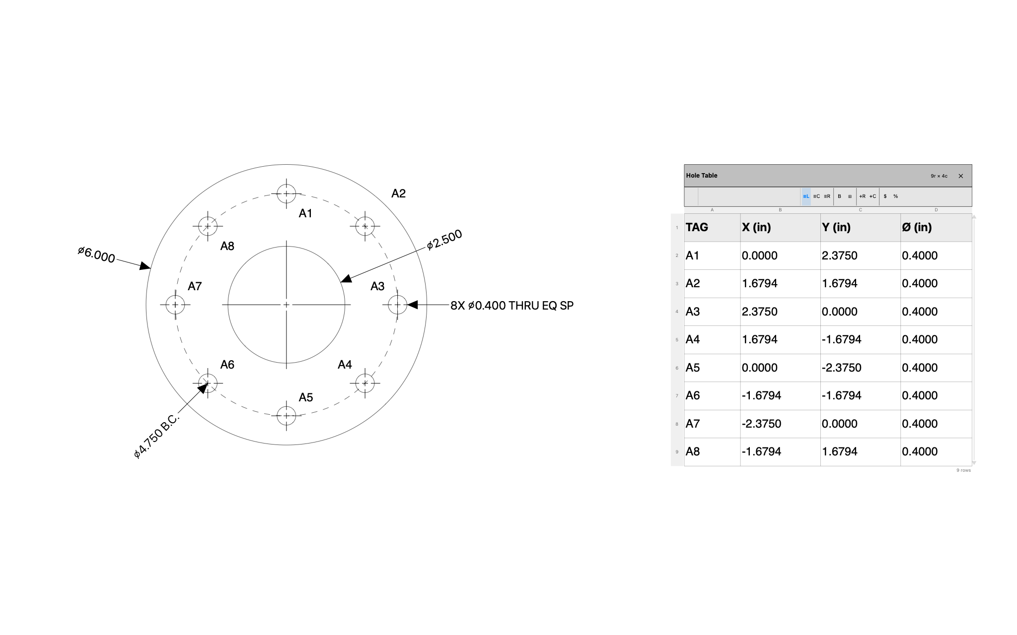
“Draw a 6-inch diameter flange centered at the origin with a 2.5-inch bore. Put eight 0.400-inch holes equally spaced on a 4.75-inch bolt circle, the first one on the positive X axis — draw one hole and polar-array it. Show the bolt circle itself as a dashed circle. Center marks on the bore and on all eight holes. Diameter dimensions on the outside, the bore and the bolt circle, the bolt circle one with the suffix "B.C.", and one diameter dimension on the first hole with the prefix "8X" and the suffix "THRU EQ SP". Then a hole table for the eight holes measured from the flange center, placed to the right. Run check_overlaps and fix anything it flags.”

What C3 drew

Bolt-circle flange with a hole table — a C3 drawing produced by C3 Assistant

Eight holes from one polar array, center marks on every hole, diameter dimensions with the 8X prefix and THRU EQ SP suffix, and a hole table listing A1 through A8 from the flange center.

03

One-bedroom apartment

Architecture

The request, verbatim

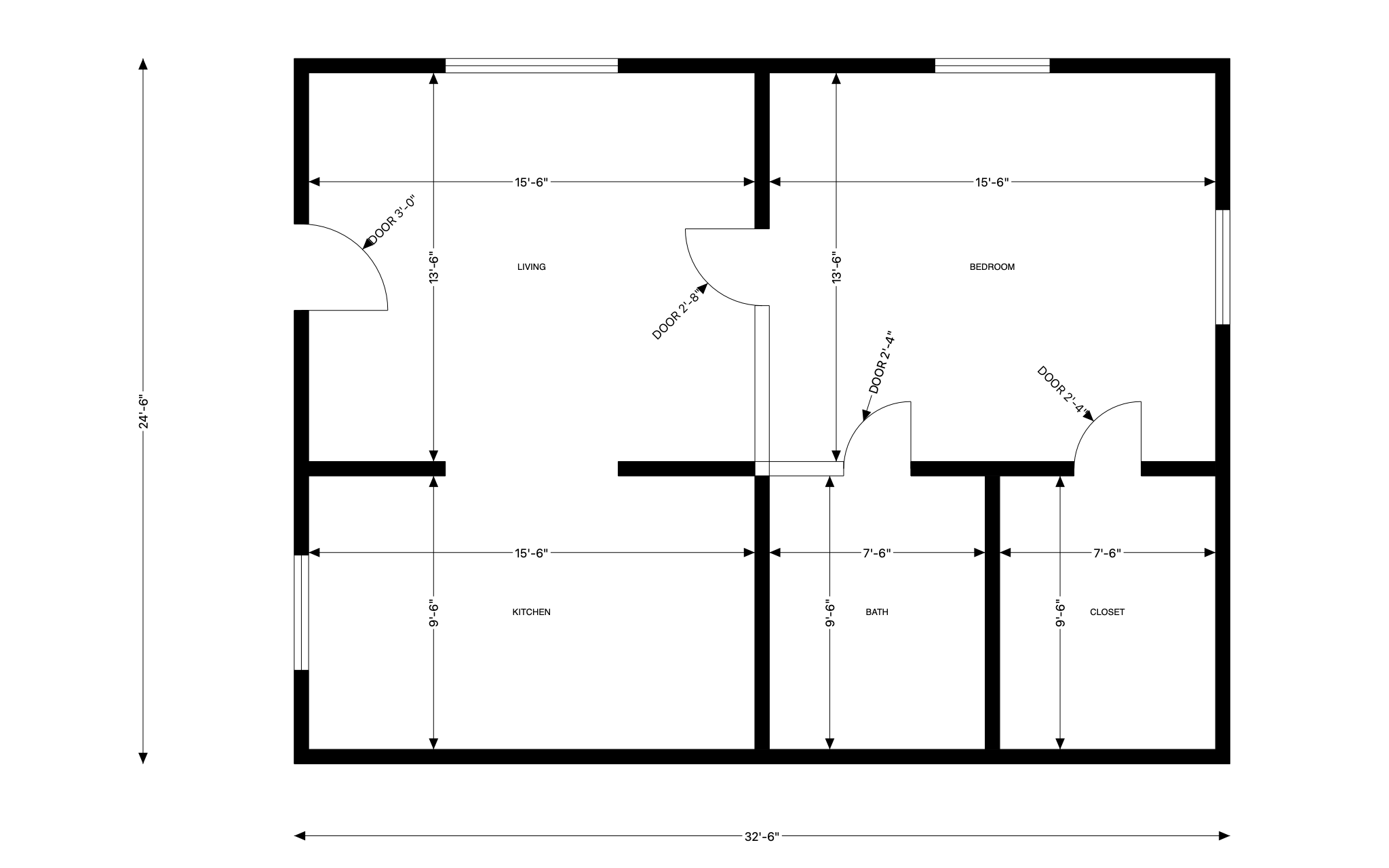
“Draw a one-bedroom apartment, 32 by 24 feet outside, with 6-inch walls, as five rooms that share their walls: LIVING 16 by 14 in the northwest corner, KITCHEN 16 by 10 below it in the southwest corner, BEDROOM 16 by 14 in the northeast corner, BATH 8 by 10 along the south wall just east of the kitchen, and CLOSET 8 by 10 in the southeast corner. Doors: a 3-foot entry door in the living room's west wall at y = 17 swinging in, a 2-foot-8 door between the living room and bedroom at 16, 17, a 2-foot-4 door from the bedroom into the bath at 20, 10, and a 2-foot-4 door from the bedroom into the closet at 28, 10. A 6-foot cased opening, no door, between the kitchen and living room centered at 8, 10. Windows: 6 feet in the living room's north wall at x = 8, 4 feet in the bedroom's north wall at x = 24, 4 feet in the bedroom's east wall at y = 17, and 4 feet in the kitchen's west wall at y = 5. Fill all the walls, auto dimension the plan, and put each room's name in its centre. Run check_overlaps and fix anything it flags.”

What C3 drew

One-bedroom apartment — a C3 drawing produced by C3 Assistant

Five rooms sharing their walls, four door swings, a cased opening, four windows, filled walls, and auto dimensions in feet and inches.

04

48-foot Warren truss

Structural engineering

The request, verbatim

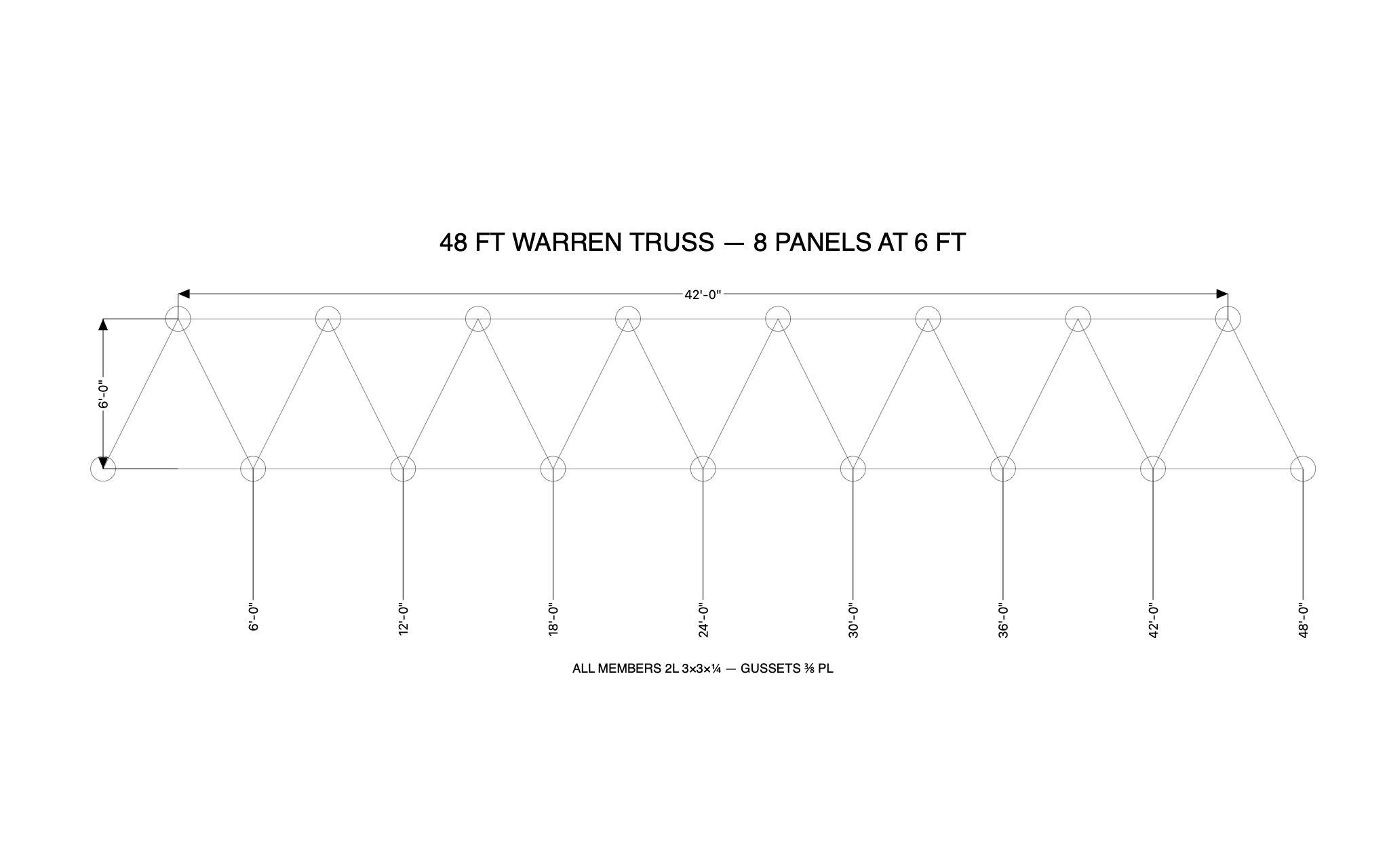
“Draw a 48-foot Warren truss, 6 feet deep, with 8 panels of 6 feet. The bottom chord runs from 0, 0 to 48, 0 and the top chord from 3, 6 to 45, 6. The web is ONE zigzag polyline starting at 0, 0, up to 3, 6, down to 6, 0, up to 9, 6 and so on every 3 feet, ending at 48, 0. Put a 6-inch radius gusset circle at every joint — nine on the bottom chord and eight on the top — drawing one and copying it along each chord. Dimension the panel points along the bottom chord as ordinate dimensions from the left end, one every 6 feet through 48, with the dimension line 3 feet below the chord; dimension the depth 6 feet at the left end, and the top chord length. Label it "48 FT WARREN TRUSS — 8 PANELS AT 6 FT" above in 1-foot text and add the note "ALL MEMBERS 2L 3×3×¼ — GUSSETS ⅜ PL" below the dimensions. Run check_overlaps and fix anything it flags.”

What C3 drew

48-foot Warren truss — a C3 drawing produced by C3 Assistant

The web is one zigzag polyline, seventeen gusset circles were copied along the chords, and the panel points read as ordinate dimensions from 6'-0" to 48'-0".

05

Parking layout, 26 stalls

Civil and site

The request, verbatim

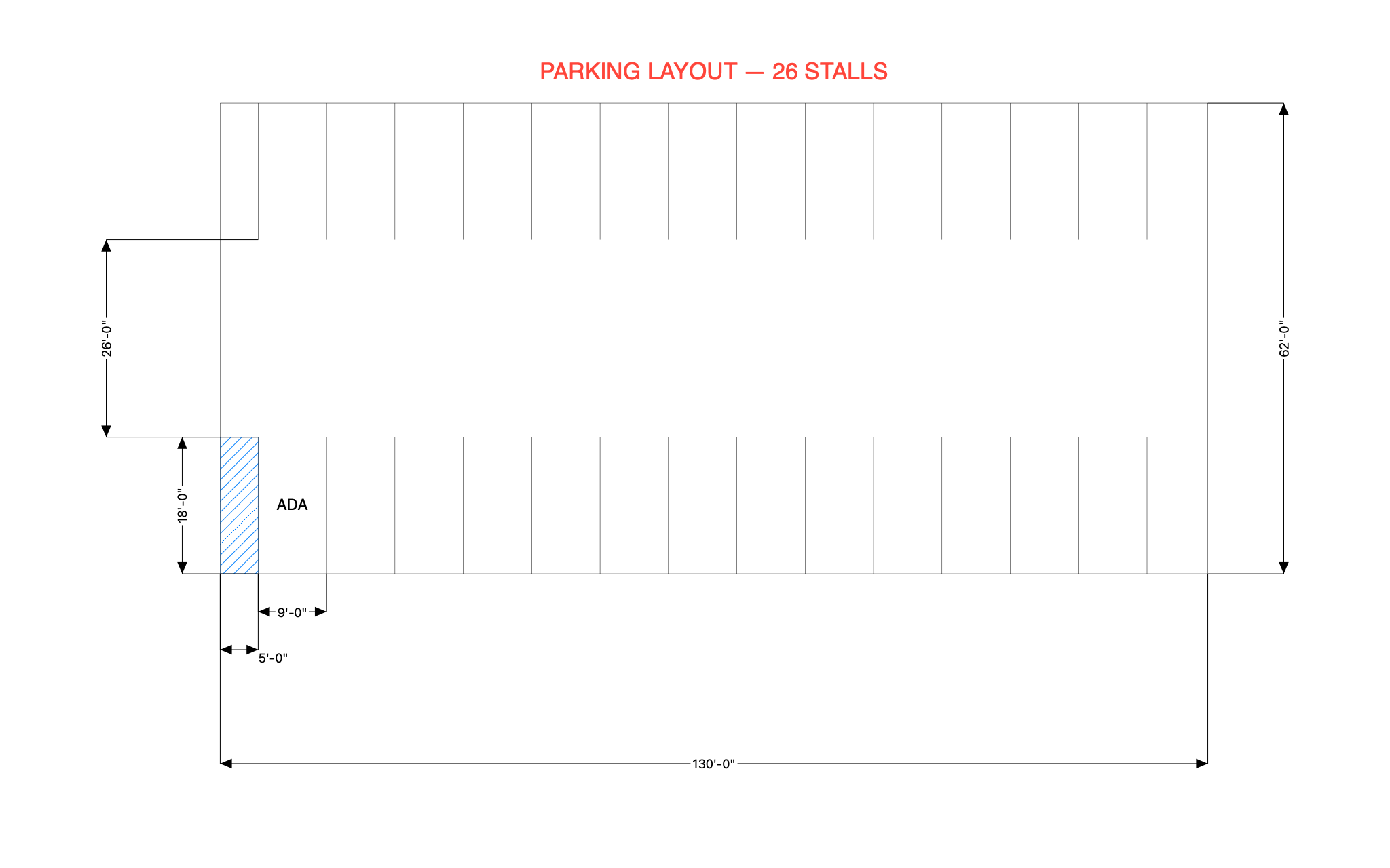
“Draw a parking lot 130 by 62 feet with the lower-left corner at the origin — the outline is the curb. Two rows of 9-foot-wide, 18-foot-deep stalls face a 26-foot drive aisle: the south row's stripes run from y = 0 to y = 18, the north row's from y = 44 to y = 62, fourteen stripes per row starting at x = 5 and every 9 feet after — draw one stripe per row and array it. That makes 13 stalls a side, with 8 feet spare at the east end. The west stall of the south row is the accessible one: the 5-foot strip between the west curb and the first stripe, from 0, 0 to 5, 18, is its access aisle — auto-hatch it with diagonal lines 1 foot apart in blue — and put "ADA" in 2-foot black text centered at 9.5, 9, the middle of that stall. Dimension one stall width, the stall depth, the drive aisle width, the 5-foot access aisle from 0, 0 to 5, 0, and the overall 130 and 62. Title it "PARKING LAYOUT — 26 STALLS" above in 3-foot red text. Run check_overlaps and fix anything it flags.”

What C3 drew

Parking layout, 26 stalls — a C3 drawing produced by C3 Assistant

Twenty-eight stripes from two arrays, the accessible aisle hatched in blue, stall, aisle and lot dimensioned in feet and inches, the title in red.

06

Five-step stair, isometric

Pictorial drawing

The request, verbatim

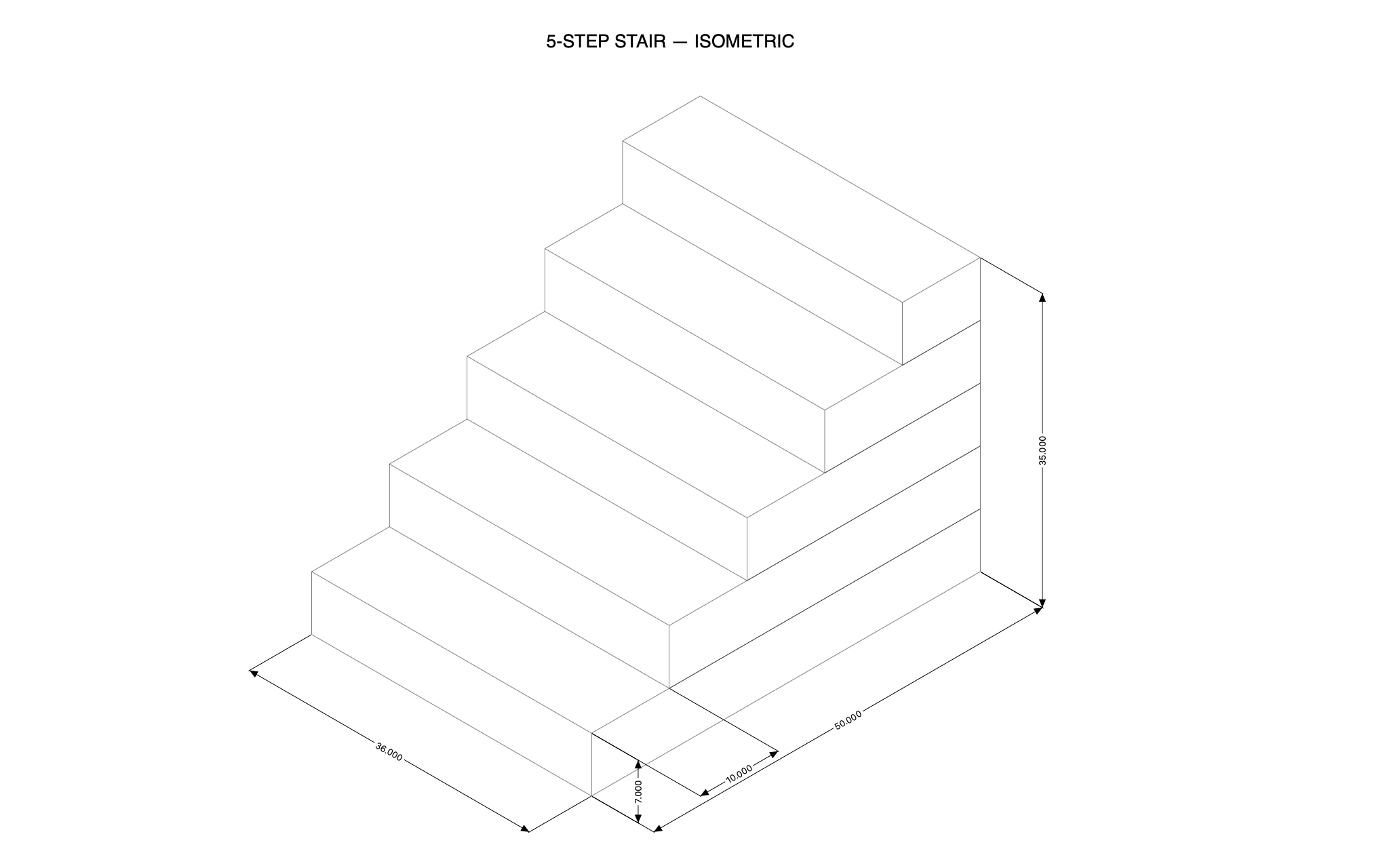
“Draw an isometric of a solid five-step staircase 36 inches wide with a 7-inch rise and a 10-inch run, rising toward the back: five boxes stacked so the bottom step is 36 wide by 50 deep by 7 high at the origin, the next 36 by 40 by 7 sitting on it set back 10, and so on to the top step 36 by 10 by 7 — hide the edges that other steps cover. Dimension one rise, one run, the width, the total depth and the total height with pictorial dimensions. Title it "5-STEP STAIR — ISOMETRIC" above. Run check_overlaps and fix anything it flags.”

What C3 drew

Five-step stair, isometric — a C3 drawing produced by C3 Assistant

Five boxes in an isometric frame with hidden lines removed between them, and pictorial dimensions that read the true 7, 10, 36, 50 and 35 inches.

07

Welded tube frame

Fabrication

The request, verbatim

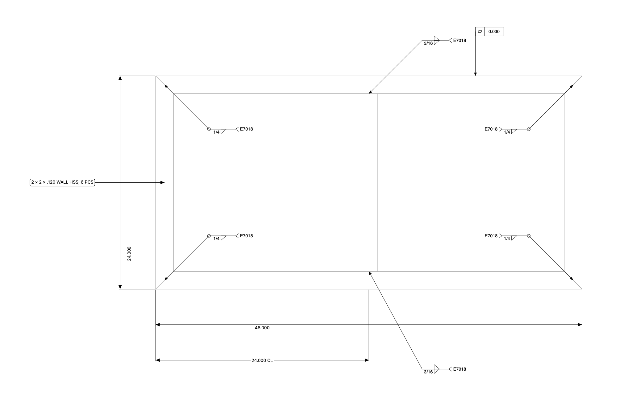
“Draw a welded frame of 2-inch square steel tube, 48 by 24 outside, lower-left at the origin: the outer rectangle, the inner rectangle 2 inches inside it, and a miter line across each corner from the outer corner to the inner corner. Add a vertical cross member of the same tube centered at x = 24, running between the top and bottom rails. Weld symbols: a 1/4-inch fillet weld all around at each of the four mitered corners, arrow to the middle of the miter line, and a 3/16 fillet weld both sides at the two tee joints where the cross member meets the rails, tail note E7018 on every symbol. A flatness feature control frame, 0.030, with a leader to the top rail. Dimension the 48 and 24 outside and the 24 to the cross member's centerline, and a leader note "2 × 2 × .120 WALL HSS, 6 PCS" pointing at the left rail. Run check_overlaps and fix anything it flags.”

What C3 drew

Welded tube frame — a C3 drawing produced by C3 Assistant

Six AWS weld symbols with E7018 tails, a flatness feature control frame, a leader note, and the frame dimensioned to the cross member's centerline.

08

Bookcase with a cut list

Woodworking

The request, verbatim

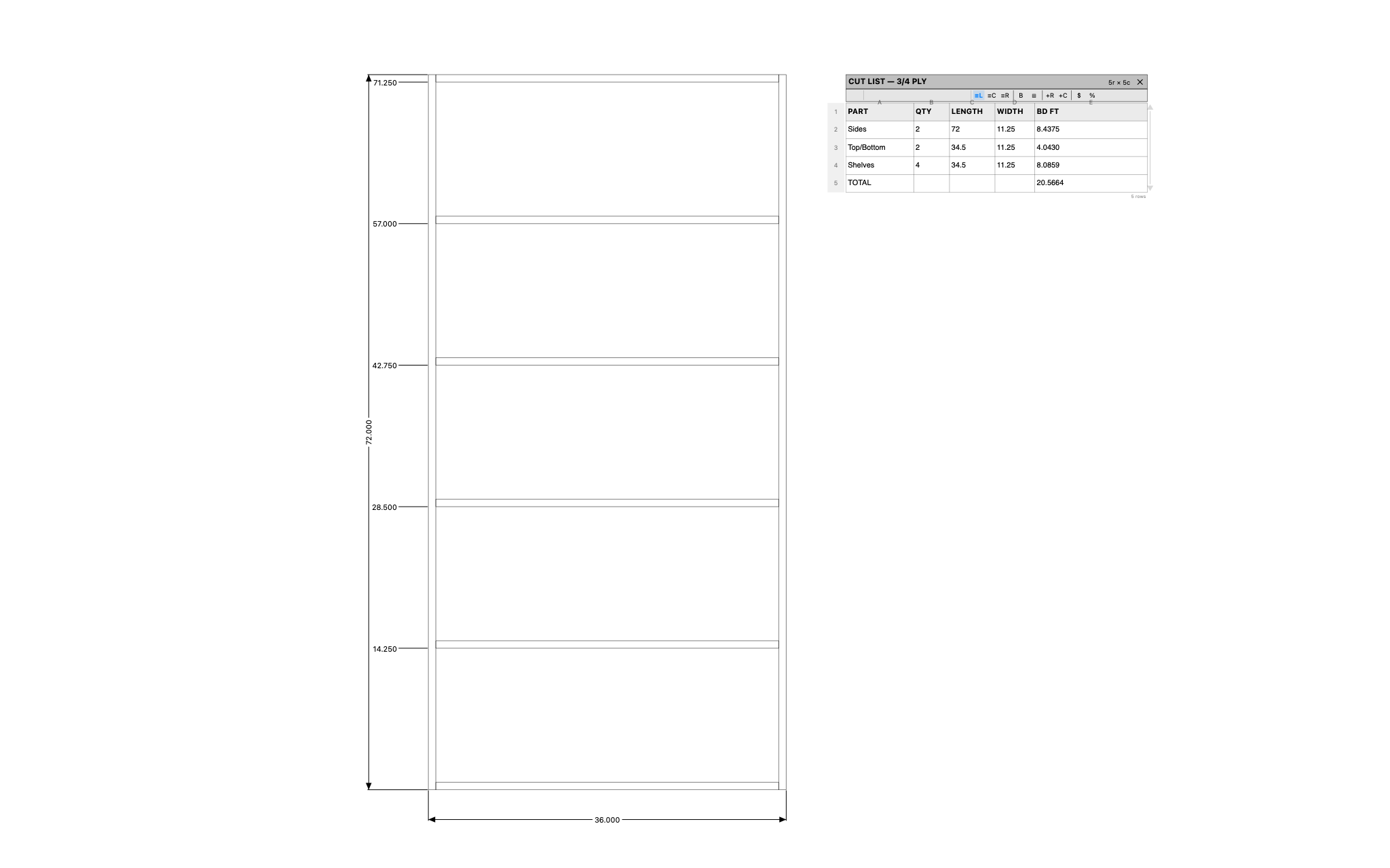
“Draw a front elevation of a bookcase 36 inches wide and 72 tall, lower-left at the origin, built from 3/4-inch stock 11-1/4 deep: two sides 3/4 by 72, a top and a bottom 34-1/2 by 3/4 between the sides, and four fixed shelves 34-1/2 by 3/4 spaced so the five openings are equal — the shelves' undersides land at 14-1/4, 28-1/2, 42-3/4 and 57; draw one shelf and array it. Dimension the shelf positions as ordinate dimensions from the bottom along the left side (the four shelf undersides and the top's underside at 71-1/4), the overall width and height. Then place a cut list table to the right titled "CUT LIST — 3/4 PLY": columns PART, QTY, LENGTH, WIDTH, BD FT, rows for the sides, top/bottom and shelves, with BD FT a formula QTY × LENGTH × WIDTH × 0.75 ÷ 144, and a TOTAL row that sums it. Run check_overlaps and fix anything it flags.”

What C3 drew

Bookcase with a cut list — a C3 drawing produced by C3 Assistant

Shelves from one array, ordinate dimensions from the floor, and a cut list table whose board-feet column is formulas with a total that sums them.

09

Spiral stair plan

Architecture

The request, verbatim

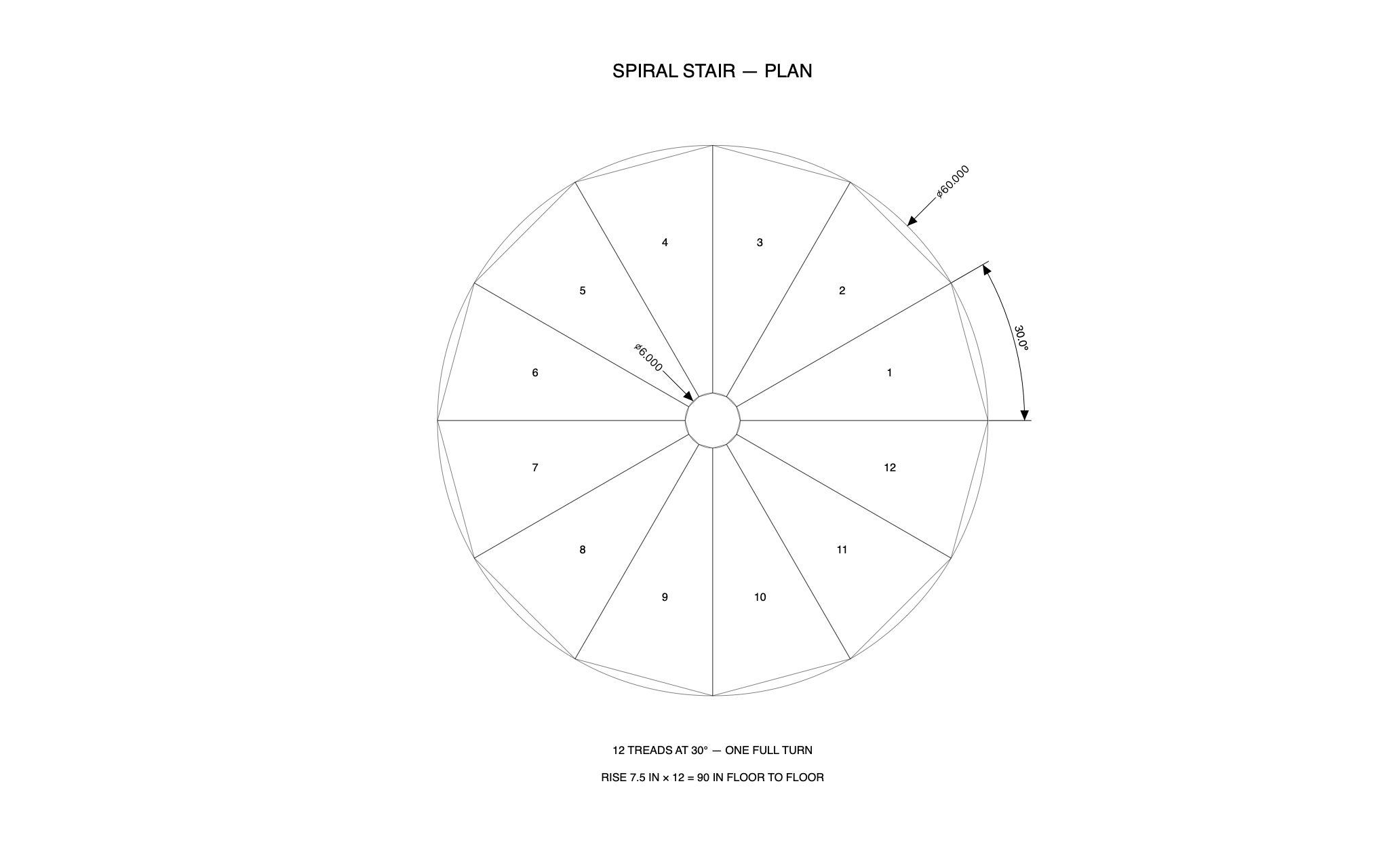
“Draw the plan view of a spiral staircase 60 inches in diameter around a 6-inch diameter center column at the origin. One tread is the polygon 3, 0 then 30, 0 then 25.981, 15 then 2.598, 1.5 — a 30-degree wedge from the column to the outside. Polar-array it into twelve treads around the origin over the full circle. Number the treads 1 through 12 counterclockwise in 1.2-inch text, each number at radius 20 on the middle of its tread. Draw the 60-inch outside circle solid and the column circle solid. Dimension the outside diameter and the column diameter, and dimension the angle between the two radial edges of tread 1 with an angular dimension at radius 34 — it must read 30°. Title it "SPIRAL STAIR — PLAN" in 2-inch text above, and two 1.2-inch notes below: "12 TREADS AT 30° — ONE FULL TURN" and "RISE 7.5 IN × 12 = 90 IN FLOOR TO FLOOR". Run check_overlaps and fix anything it flags.”

What C3 drew

Spiral stair plan — a C3 drawing produced by C3 Assistant

Twelve treads from one polar array, numbered counterclockwise, with ø60.000, ø6.000 and a 30.0° angular dimension.

17 disciplines it was never taught.

Physics, optics, chemistry, crystallography, navigation, biology, computer science. None of these are C3 features. They are drafted from C3’s general vocabulary: lines, arcs, circles, polygons, dashed linetypes, text, dimensions. The request carries the domain knowledge. The Assistant carries the drafting.

10

Free-body diagram, block on a 30° incline

Physics

The request, verbatim

“Draw a physics free-body diagram of a block resting on a 30-degree incline, in two parts side by side. Show the whole request (398 words)

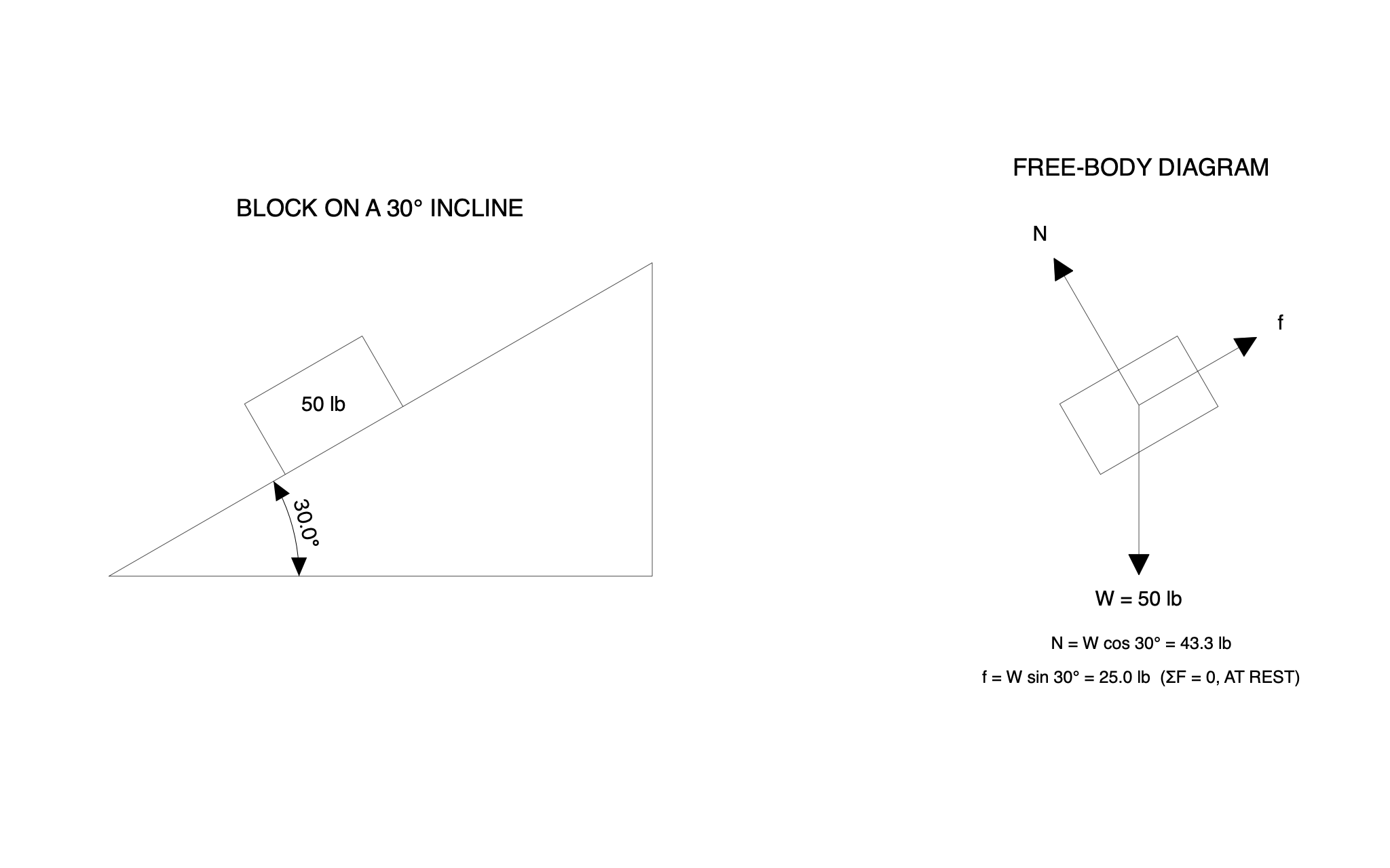
LEFT, the situation sketch: a right triangle for the incline with the ground from 0, 0 to 8, 0, a vertical from 8, 0 to 8, 4.619, and the slope from 0, 0 up to 8, 4.619 — but draw the slope line in two pieces, 0, 0 to 2.598, 1.5 and 4.330, 2.5 to 8, 4.619, because the block sits on it between those points. The block is a polygon with corners 2.598, 1.5 then 4.330, 2.5 then 3.730, 3.539 then 1.998, 2.539 — its bottom face IS the slope under it. Put the text "50 lb" in 0.3-inch letters centered inside the block at 3.164, 2.520. Dimension the incline angle with an angular dimension between the ground line and the lower slope piece, arc 1.5 inches from the corner at 0, 0 — it must read 30°. Title the sketch "BLOCK ON A 30° INCLINE" in 0.35-inch text centered at 4, 5.4. RIGHT, the free-body diagram: the same block shifted 12 inches right — corners 14.598, 1.5 then 16.330, 2.5 then 15.730, 3.539 then 13.998, 2.539 — with NO incline drawn, and three force vectors starting at the block's centre 15.164, 2.520, each a line plus a FILLED triangle arrowhead — filled solid black, not an outline. Weight W straight down: shaft from the centre to 15.164, 0.320, arrowhead with corners 15.014, 0.320 and 15.314, 0.320 and tip 15.164, 0.020, label "W = 50 lb" in 0.3-inch text centered at 15.164, -0.35. Normal force N perpendicular to the slope, up and to the left: shaft from the centre to 14.064, 4.425, arrowhead corners 14.194, 4.500 and 13.934, 4.350, tip 13.914, 4.685, label "N" centered at 13.71, 5.03. Friction f up the slope: shaft from the centre to 16.636, 3.370, arrowhead corners 16.561, 3.500 and 16.711, 3.240, tip 16.896, 3.520, label "f" centered at 17.25, 3.72. Title it "FREE-BODY DIAGRAM" in 0.35-inch text at 15.2, 6.0. Below it two 0.25-inch notes: "N = W cos 30° = 43.3 lb" at 15.2, -1.0 and "f = W sin 30° = 25.0 lb (ΣF = 0, AT REST)" at 15.2, -1.5. The vectors are allowed to cross the block's outline — that is how a free-body diagram is drawn. Run check_overlaps when you are done and fix anything it flags.”

What C3 drew

Free-body diagram, block on a 30° incline — a C3 drawing produced by C3 Assistant

Situation sketch on the left, free-body diagram on the right, filled arrowheads, an angular dimension reading 30.0°.

11

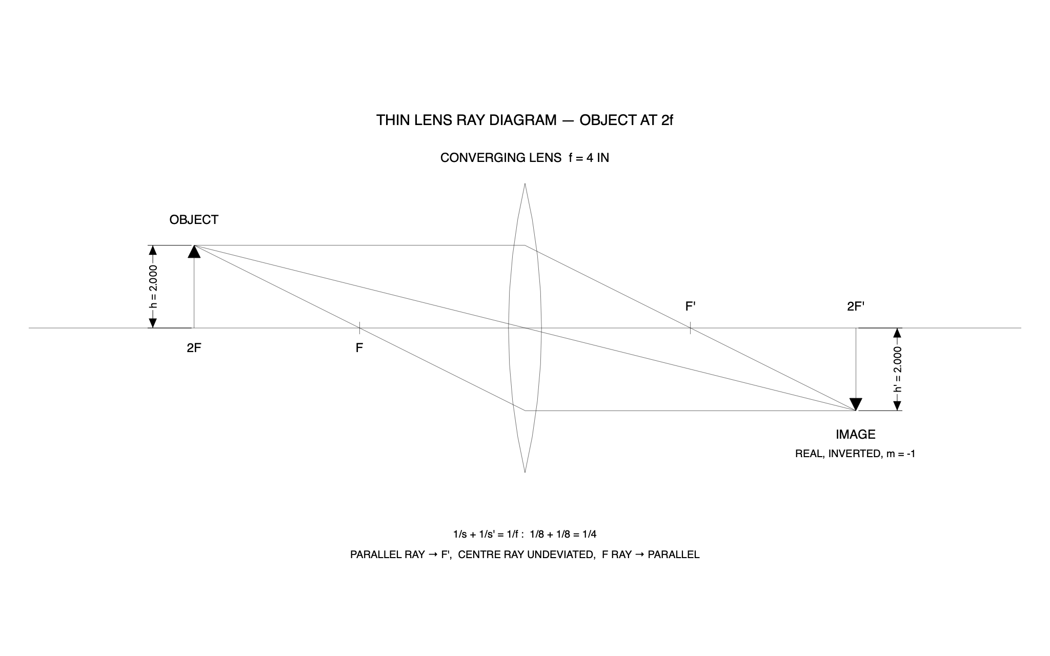
Thin-lens ray diagram, object at 2f

Optics

The request, verbatim

“Draw an optics ray diagram of a thin converging lens forming a real image. Show the whole request (456 words)

The optical axis is a horizontal line from -12, 0 to 12, 0. The lens is at x = 0, drawn double-convex as two arcs meeting at 0, 3.5 and 0, -3.5: the right surface is an arc centered at -15.113, 0 with radius 15.513 from -13.04° to 13.04°, the left surface is an arc centered at 15.113, 0 with radius 15.513 from 166.96° to 193.04°. Mark the focal points with short vertical ticks 0.3 tall crossing the axis at -4, 0 and 4, 0, labeled "F" in 0.3-inch text centered at -4, -0.5 and "F'" centered at 4, 0.5. Label "2F" centered at -8, -0.5 and "2F'" centered at 8, 0.5. The OBJECT is an upright arrow at x = -8: a line from -8, 0 to -8, 1.7 with a FILLED triangle arrowhead — filled solid black, not an outline — corners -8.15, 1.7 and -7.85, 1.7, tip -8, 2.0; label "OBJECT" in 0.3-inch text centered at -8, 2.6. The IMAGE is an inverted arrow at x = 8: a line from 8, 0 to 8, -1.7 with a filled arrowhead, corners 7.85, -1.7 and 8.15, -1.7, tip 8, -2.0; label "IMAGE" centered at 8, -2.6 and "REAL, INVERTED, m = -1" in 0.25-inch text centered at 8, -3.05. Now the three principal rays, all starting at the object tip -8, 2: ray 1 runs parallel to the axis from -8, 2 to 0, 2 and then bends through F' to the image tip, a line from 0, 2 to 8, -2. Ray 2 goes straight through the centre of the lens undeviated, one line from -8, 2 to 8, -2. Ray 3 passes through F on its way to the lens, a line from -8, 2 to 0, -2, and leaves parallel to the axis, a line from 0, -2 to 8, -2. Dimension the object height with a vertical dimension from -8, 0 to -8, 2, offset 1 inch to the left, prefix "h = ", and the image height with a vertical dimension from 8, 0 to 8, -2, offset 1 inch to the right, prefix "h' = ". Label the lens "CONVERGING LENS f = 4 IN" in 0.3-inch text centered at 0, 4.1 and title the drawing "THIN LENS RAY DIAGRAM — OBJECT AT 2f" in 0.35-inch text centered at 0, 5.0. Two 0.25-inch notes below: "1/s + 1/s' = 1/f : 1/8 + 1/8 = 1/4" at 0, -5.0 and "PARALLEL RAY → F', CENTRE RAY UNDEVIATED, F RAY → PARALLEL" at 0, -5.5. Rays crossing the lens and each other is correct. Run check_overlaps when you are done and fix anything it flags.”

What C3 drew

Thin-lens ray diagram, object at 2f — a C3 drawing produced by C3 Assistant

A double-convex lens drawn as two arcs, three principal rays converging at the image tip, h and h' dimensioned at 2.000.

12

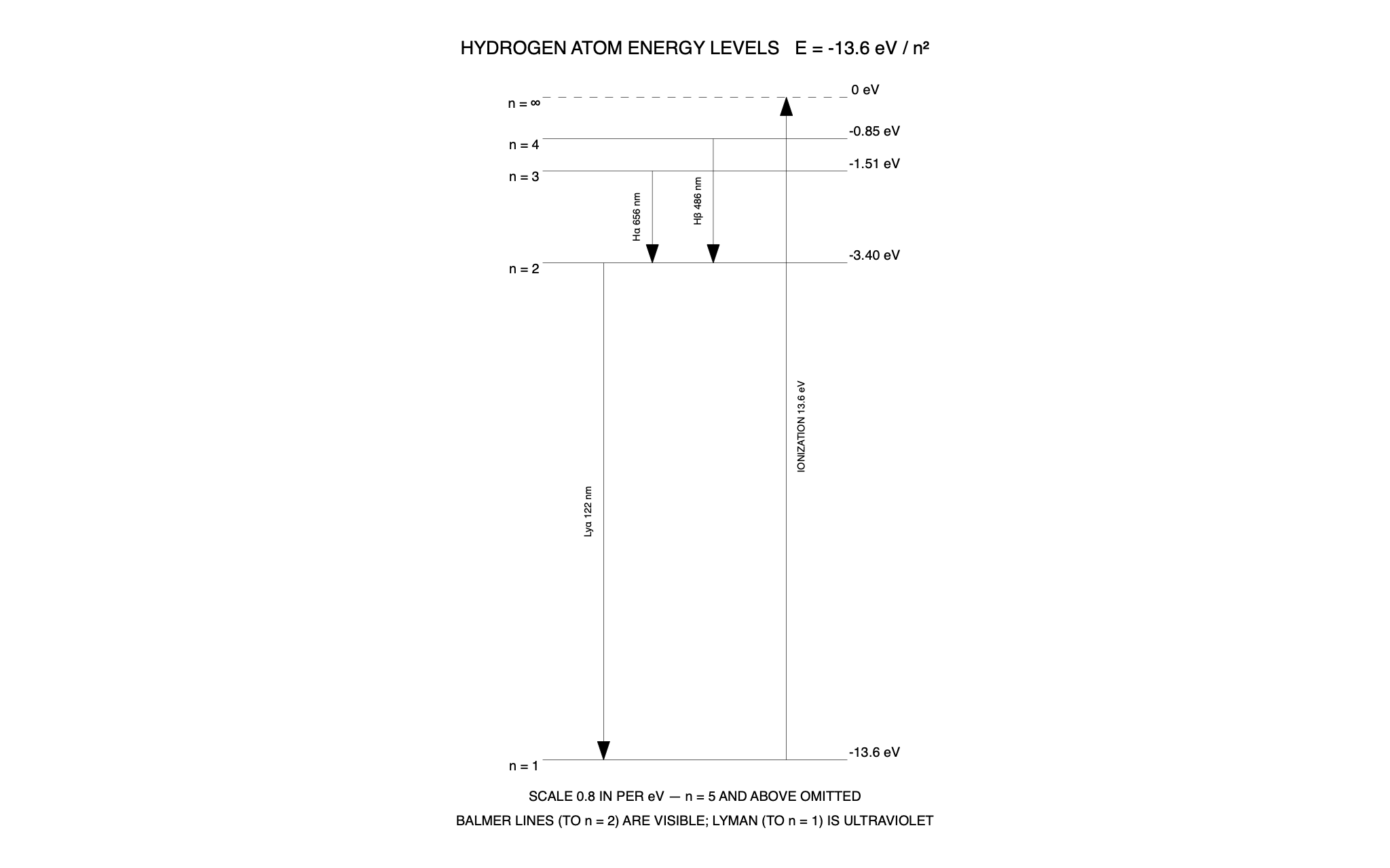
Hydrogen atom energy levels

Atomic physics

The request, verbatim

“Draw a hydrogen-atom energy-level diagram. Show the whole request (406 words)

Five horizontal level lines, each from x = 0 to x = 5: n = ∞ at y = 0 drawn DASHED, n = 4 at y = -0.68, n = 3 at y = -1.209, n = 2 at y = -2.72 and n = 1 at y = -10.88 — these are E = -13.6 eV / n² at 0.8 inches per eV. Label each level on the left with 0.22-inch text right-justified at x = -0.3 on the level's y: "n = ∞", "n = 4", "n = 3", "n = 2", "n = 1"; and on the right with 0.22-inch text left-justified at x = 5.3: "0 eV", "-0.85 eV", "-1.51 eV", "-3.40 eV", "-13.6 eV". Then four transitions, each a vertical line plus a FILLED triangle arrowhead 0.2 wide and 0.3 tall — filled solid black, not an outline — with its tip ON the destination level. Lyman-alpha, n = 2 to n = 1, at x = 1.0: shaft from 1.0, -2.72 down to 1.0, -10.58, arrowhead corners 0.9, -10.58 and 1.1, -10.58, tip 1.0, -10.88. H-alpha, n = 3 to n = 2, at x = 1.8: shaft from 1.8, -1.209 to 1.8, -2.42, arrowhead corners 1.7, -2.42 and 1.9, -2.42, tip 1.8, -2.72. H-beta, n = 4 to n = 2, at x = 2.8: shaft from 2.8, -0.68 to 2.8, -2.42, arrowhead corners 2.7, -2.42 and 2.9, -2.42, tip 2.8, -2.72. Ionization, n = 1 up to n = ∞, at x = 4.0 pointing UP: shaft from 4.0, -10.88 to 4.0, -0.30, arrowhead corners 3.9, -0.30 and 4.1, -0.30, tip 4.0, 0. Label each transition with 0.16-inch text rotated 90 degrees so it reads upward, centered 0.25 to the left of its shaft at mid-height: "Lyα 122 nm" at 0.75, -6.8; "Hα 656 nm" at 1.55, -1.96; "Hβ 486 nm" at 2.55, -1.7; and "IONIZATION 13.6 eV" centered 0.25 to the RIGHT of its shaft at 4.25, -5.4. Title "HYDROGEN ATOM ENERGY LEVELS E = -13.6 eV / n²" in 0.3-inch text centered at 2.5, 0.8. Two 0.22-inch notes below: "SCALE 0.8 IN PER eV — n = 5 AND ABOVE OMITTED" at 2.5, -11.5 and "BALMER LINES (TO n = 2) ARE VISIBLE; LYMAN (TO n = 1) IS ULTRAVIOLET" at 2.5, -11.9. Arrows crossing level lines is correct. Run check_overlaps when you are done and fix anything it flags.”

What C3 drew

Hydrogen atom energy levels — a C3 drawing produced by C3 Assistant

Five levels at 0.8 inches per electron-volt, three emission arrows and one ionization arrow, wavelength labels reading upward.

13

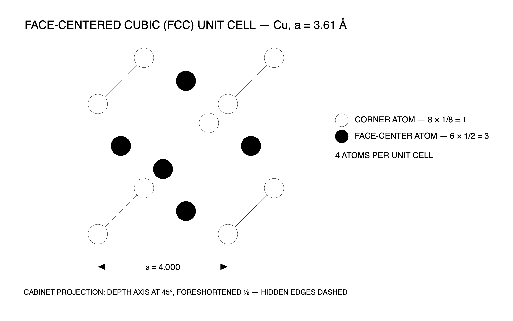
Face-centered cubic unit cell

Crystallography

The request, verbatim

“Draw a face-centered cubic unit cell as a crystallographer draws it, a cube in cabinet projection. Show the whole request (371 words)

The front face is the square with corners 0, 0 and 4, 0 and 4, 4 and 0, 4; the back face is the same square shifted by 1.414, 1.414, so its corners are 1.414, 1.414 and 5.414, 1.414 and 5.414, 5.414 and 1.414, 5.414. Draw the twelve cube edges as separate lines: the four front-face edges, the four back-face edges, and the four depth edges joining each front corner to its back corner. Three of them are hidden behind the front face and must be DASHED: the back-bottom edge from 1.414, 1.414 to 5.414, 1.414, the back-left vertical from 1.414, 1.414 to 1.414, 5.414, and the depth edge from 0, 0 to 1.414, 1.414. Atoms are circles of radius 0.3: an OPEN circle at each of the eight corners, and a FILLED circle — filled solid black — at each of the six face centres: front 2, 2; back 3.414, 3.414; left 0.707, 2.707; right 4.707, 2.707; top 2.707, 4.707; bottom 2.707, 0.707. The back corner atom at 1.414, 1.414 and the back-face atom at 3.414, 3.414 are hidden, so draw those two circles dashed and leave the back-face one unfilled. Every edge stops at the surface of the atom at each end — 0.3 short of the corner — so no line runs into a circle. Dimension the front-bottom edge from 0, 0 to 4, 0 with a linear dimension offset 1 inch below, prefix "a = ". Title it "FACE-CENTERED CUBIC (FCC) UNIT CELL — Cu, a = 3.61 Å" in 0.35-inch text centered at 2.7, 6.4. Add a legend to the right in 0.25-inch text, left-justified: an open circle of radius 0.2 at 7.5, 3.5 with "CORNER ATOM — 8 × 1/8 = 1" starting at 7.9, 3.5; a filled circle of radius 0.2 at 7.5, 3.0 with "FACE-CENTER ATOM — 6 × 1/2 = 3" starting at 7.9, 3.0; and "4 ATOMS PER UNIT CELL" starting at 7.3, 2.4. One 0.22-inch note below: "CABINET PROJECTION: DEPTH AXIS AT 45°, FORESHORTENED ½ — HIDDEN EDGES DASHED" centered at 2.7, -1.8. Run check_overlaps when you are done and fix anything it flags.”

What C3 drew

Face-centered cubic unit cell — a C3 drawing produced by C3 Assistant

A cube in cabinet projection, open corner atoms, filled face-center atoms, hidden edges dashed, the front edge dimensioned a = 4.000.

14

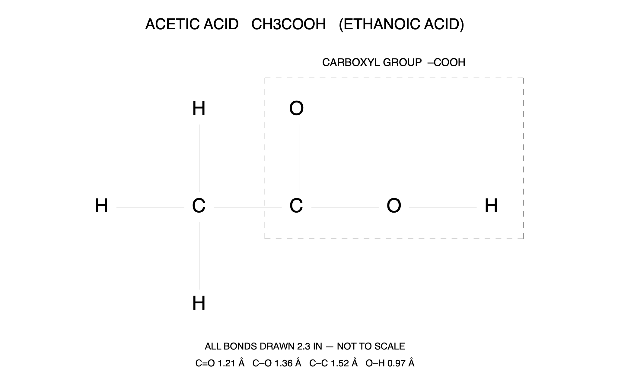
Acetic acid structural formula

Organic chemistry

The request, verbatim

“Draw the structural formula of acetic acid, CH3COOH, the way an organic chemist draws it, with every atom shown. Show the whole request (255 words)

Atoms are 0.45-inch letters centered exactly at these points: C at 0, 0; H at -2.3, 0; H at 0, 2.3; H at 0, -2.3; C at 2.3, 0; O at 2.3, 2.3; O at 4.6, 0; H at 6.9, 0. Bonds are lines between atom centres that stop 0.35 inches short of the letters at both ends: the three C–H bonds from the first carbon to its three hydrogens, the C–C bond from 0, 0 to 2.3, 0, the C–O single bond from 2.3, 0 to 4.6, 0, and the O–H bond from 4.6, 0 to 6.9, 0. The C=O DOUBLE bond from 2.3, 0 up to 2.3, 2.3 is two parallel lines 0.16 apart — one at x = 2.22 and one at x = 2.38, each from y = 0.35 to y = 1.95. Enclose the carboxyl group with a DASHED rectangle from 1.55, -0.75 to 7.65, 3.05 and label it "CARBOXYL GROUP –COOH" in 0.25-inch text centered at 4.6, 3.4. Title "ACETIC ACID CH3COOH (ETHANOIC ACID)" in 0.35-inch text centered at 2.5, 4.3. Two 0.22-inch notes below: "ALL BONDS DRAWN 2.3 IN — NOT TO SCALE" at 2.5, -3.3 and "C=O 1.21 Å C–O 1.36 Å C–C 1.52 Å O–H 0.97 Å" at 2.5, -3.7. The C–C bond crossing the dashed box is correct. Do not put circles around the letters. Run check_overlaps when you are done and fix anything it flags.”

What C3 drew

Acetic acid structural formula — a C3 drawing produced by C3 Assistant

Every atom shown, bonds stopping short of the letters, the double bond as two parallel lines, the carboxyl group boxed.

15

Four-bar linkage, crank-rocker at 60°

Mechanical engineering

The request, verbatim

“Draw a kinematic diagram of a four-bar linkage. Show the whole request (399 words)

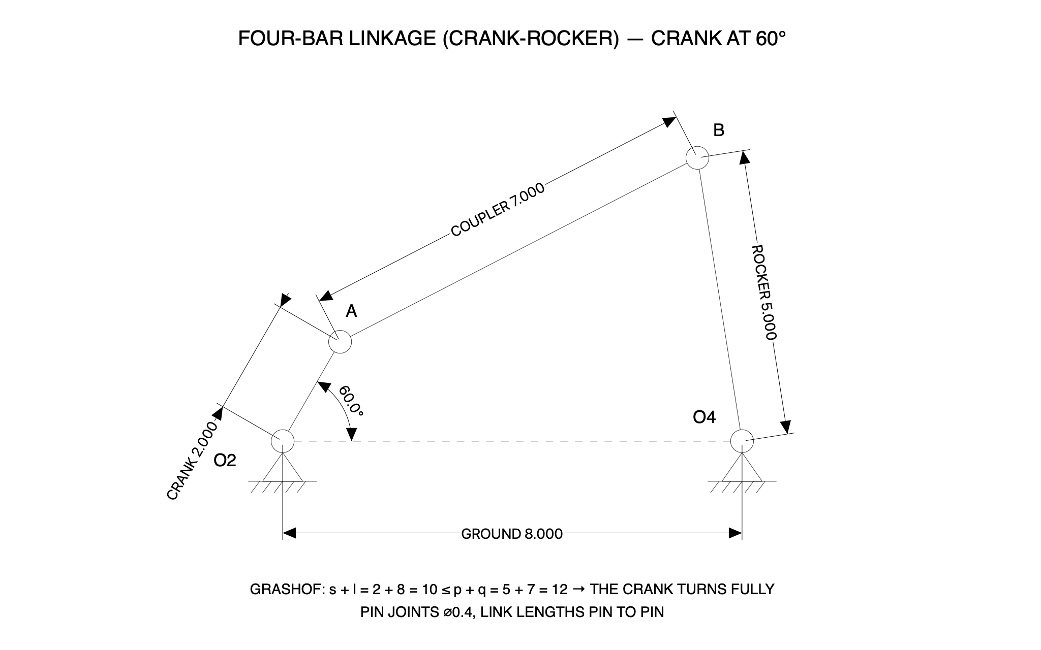
The pin joints are at O2 = 0, 0 (ground pivot), A = 1.000, 1.732 (crank pin), B = 7.2221, 4.939 (rocker pin) and O4 = 8, 0 (ground pivot); draw a circle of radius 0.2 at each. The links are lines between pin centres that stop at the circles, 0.2 short of each centre: the crank O2–A, the coupler A–B and the rocker B–O4 as solid lines, and the ground link O2–O4 as a DASHED line. Put a ground symbol under each ground pivot: an open triangle with its apex 0.2 below the pivot and a base 0.7 wide 0.5 lower — for O2 the apex at 0, -0.2 and base corners -0.35, -0.7 and 0.35, -0.7 — a ground line 1.2 long under the base from -0.6, -0.7 to 0.6, -0.7, and five short hatch ticks below it, each from a point on the ground line down-left to 0.15 left and 0.2 below, at x = -0.4, -0.2, 0, 0.2 and 0.4; the same symbol shifted 8 to the right under O4. Label the joints in 0.3-inch text: "O2" centered at -1.0, -0.35; "A" at 1.2, 2.25; "B" at 7.6, 5.4; "O4" at 7.35, 0.4. Dimension every link with an aligned dimension, pin centre to pin centre, offset 0.8 to the outside of the mechanism, with a prefix naming the link: the crank from 0, 0 to 1.000, 1.732 prefix "CRANK ", the coupler from 1.000, 1.732 to 7.2221, 4.939 prefix "COUPLER ", the rocker from 7.2221, 4.939 to 8, 0 prefix "ROCKER ", and the ground from 0, 0 to 8, 0 as a horizontal dimension offset 1.6 below prefix "GROUND ". They must read 2.000, 7.000, 5.000 and 8.000. Dimension the crank angle with an angular dimension between the ground link and the crank at O2, arc 1.2 inches from O2 — it must read 60°. Title "FOUR-BAR LINKAGE (CRANK-ROCKER) — CRANK AT 60°" in 0.35-inch text centered at 4, 7.0. Two 0.25-inch notes below: "GRASHOF: s + l = 2 + 8 = 10 ≤ p + q = 5 + 7 = 12 → THE CRANK TURNS FULLY" at 4, -2.6 and "PIN JOINTS ⌀0.4, LINK LENGTHS PIN TO PIN" at 4, -3.0. Run check_overlaps when you are done; if a joint label is flagged, move it just clear, and fix anything else it flags.”

What C3 drew

Four-bar linkage, crank-rocker at 60° — a C3 drawing produced by C3 Assistant

Pin joints, hatched ground symbols, and aligned dimensions that read CRANK 2.000, COUPLER 7.000, ROCKER 5.000 and GROUND 8.000.

16

Euclid, Elements I.1

Mathematics

The request, verbatim

“Draw Euclid's first construction, an equilateral triangle on a given segment, the way a geometry textbook shows it. Show the whole request (268 words)

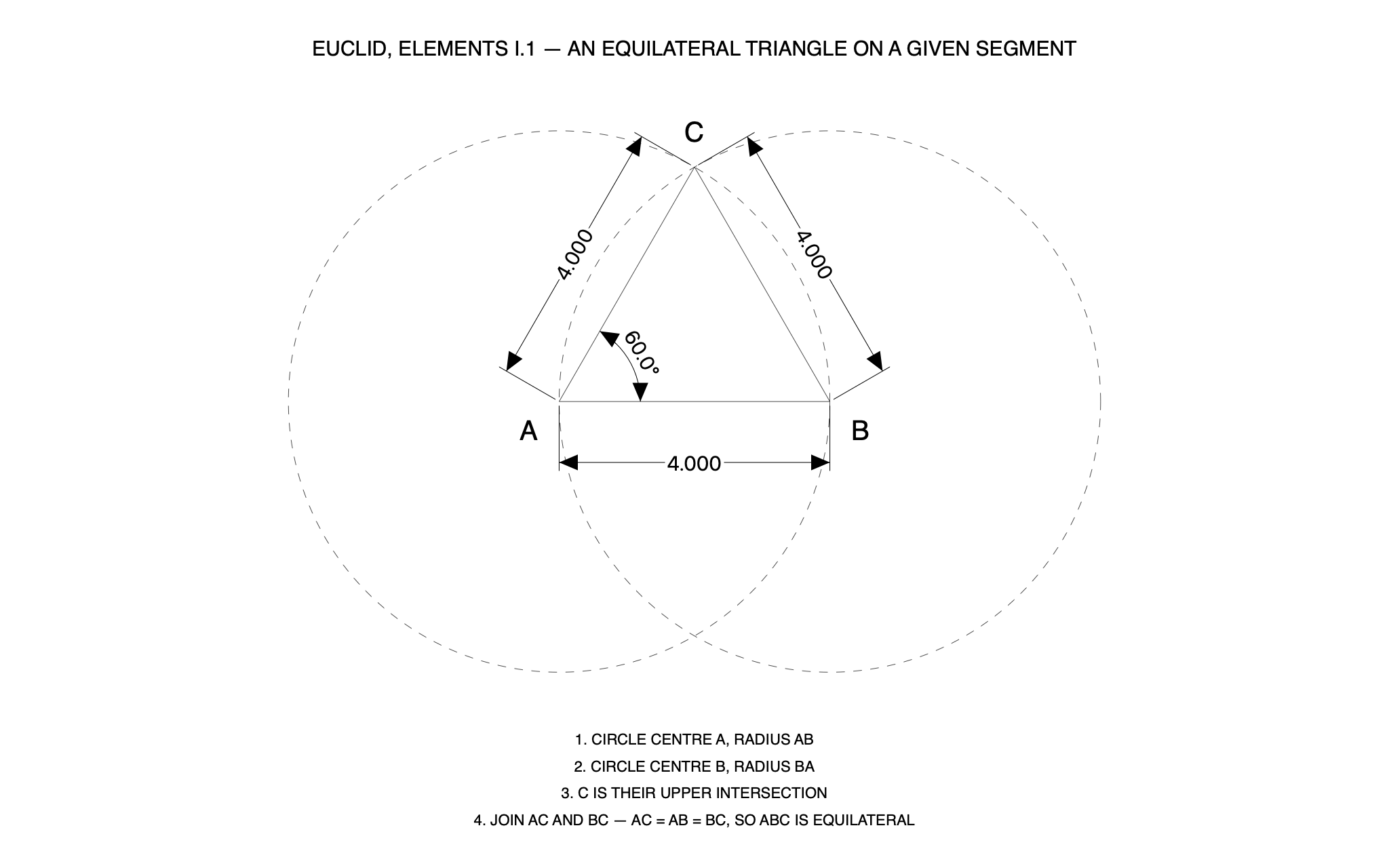
The given segment AB is a line from 0, 0 to 4, 0. Draw the two construction circles DASHED: one centered at 0, 0 with radius 4 and one centered at 4, 0 with radius 4. Their upper intersection is C at 2, 3.464; draw the sides AC from 0, 0 to 2, 3.464 and BC from 4, 0 to 2, 3.464 as solid lines. Label the points in 0.4-inch text: "A" centered at -0.45, -0.45, "B" at 4.45, -0.45, "C" at 2, 3.95. Dimension all three sides: AB with a horizontal dimension offset 0.8 below; AC with an aligned dimension from 0, 0 to 2, 3.464 offset 0.8 to the outside (up-left); CB with an aligned dimension from 2, 3.464 to 4, 0 offset 0.8 to the outside (up-right). All three must read 4.000. Dimension the angle at A between AB and AC with an angular dimension, arc 1.2 inches from A — it must read 60°. Title "EUCLID, ELEMENTS I.1 — AN EQUILATERAL TRIANGLE ON A GIVEN SEGMENT" in 0.3-inch text centered at 2, 5.2. Then the construction steps as four 0.22-inch notes centered at x = 2: "1. CIRCLE CENTRE A, RADIUS AB" at y = -5.0; "2. CIRCLE CENTRE B, RADIUS BA" at y = -5.4; "3. C IS THEIR UPPER INTERSECTION" at y = -5.8; "4. JOIN AC AND BC — AC = AB = BC, SO ABC IS EQUILATERAL" at y = -6.2. Run check_overlaps when you are done and fix anything it flags.”

What C3 drew

Euclid, Elements I.1 — a C3 drawing produced by C3 Assistant

Two dashed construction circles, the equilateral triangle between them, three sides dimensioned 4.000, one angle at 60.0°.

17

Inner solar system, plan view

Astronomy

The request, verbatim

“Draw a schematic of the inner solar system as seen from above the ecliptic. Show the whole request (258 words)

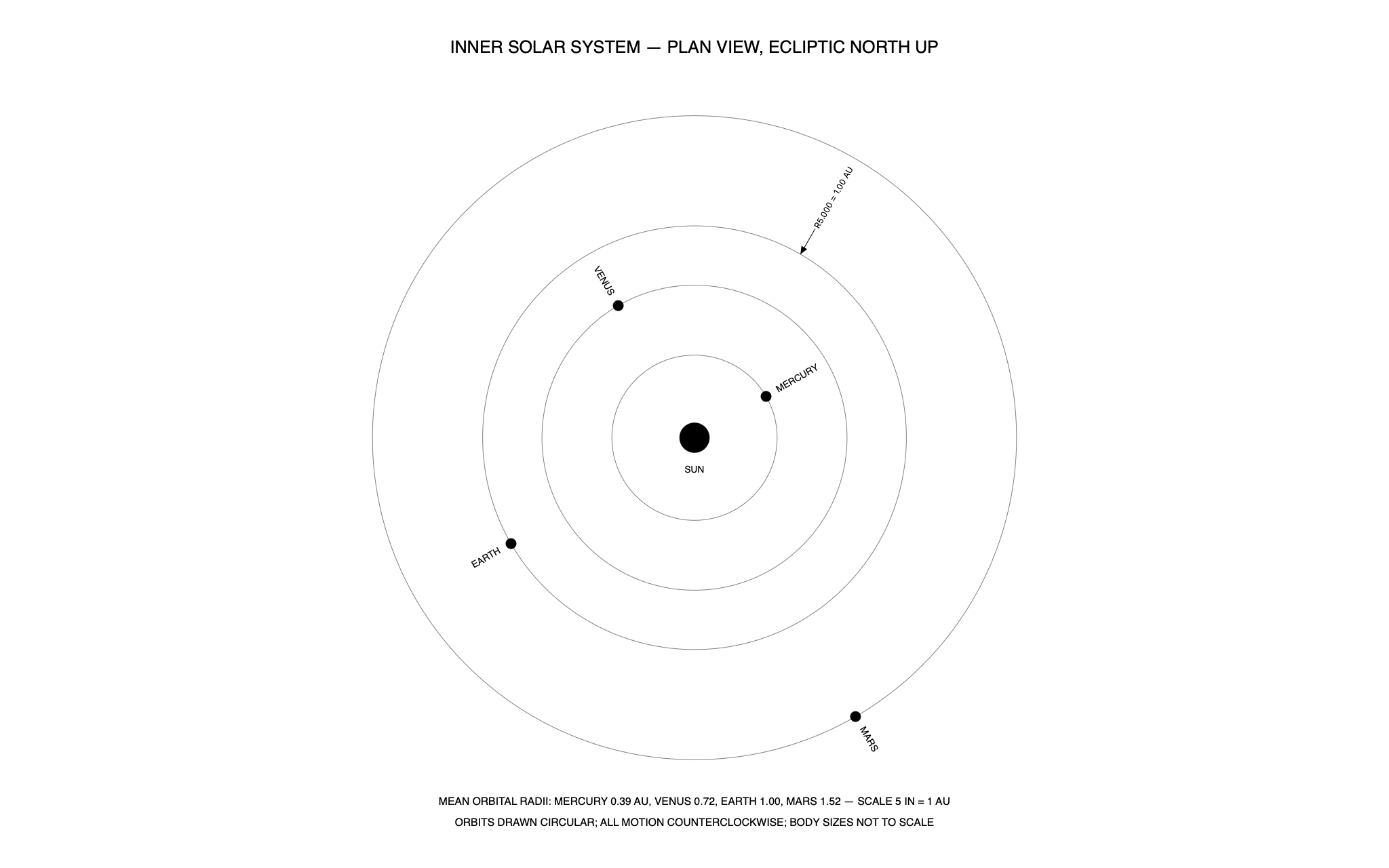
The Sun is a FILLED circle of radius 0.35 at 0, 0 — filled solid black — labeled "SUN" in 0.22-inch text centered at 0, -0.75. Four circular orbits centered at 0, 0 with radii 1.95, 3.60, 5.00 and 7.60 (that is 5 inches per AU: 0.39, 0.72, 1.00 and 1.52 AU). Planets are filled circles of radius 0.12: Mercury at 1.689, 0.975; Venus at -1.800, 3.118; Earth at -4.330, -2.500; Mars at 3.800, -6.582. Label each planet with 0.22-inch text running along its radius, outward from the planet and reading right-side up: "MERCURY" rotated 30 degrees, middle-left anchored at 1.949, 1.125; "VENUS" rotated -60 degrees, middle-right anchored at -1.950, 3.377; "EARTH" rotated 30 degrees, middle-right anchored at -4.590, -2.650; "MARS" rotated -60 degrees, middle-left anchored at 3.950, -6.841. Dimension the radius of Earth's orbit with a radius dimension at 60 degrees (up and to the right, where no planet sits) with the suffix " = 1.00 AU", so it reads R5.000 = 1.00 AU. Title "INNER SOLAR SYSTEM — PLAN VIEW, ECLIPTIC NORTH UP" in 0.4-inch text centered at 0, 9.2. Two 0.25-inch notes below: "MEAN ORBITAL RADII: MERCURY 0.39 AU, VENUS 0.72, EARTH 1.00, MARS 1.52 — SCALE 5 IN = 1 AU" at 0, -8.6 and "ORBITS DRAWN CIRCULAR; ALL MOTION COUNTERCLOCKWISE; BODY SIZES NOT TO SCALE" at 0, -9.1. The radius dimension's line crossing the inner orbits is fine. Run check_overlaps when you are done and fix anything it flags.”

What C3 drew

Inner solar system, plan view — a C3 drawing produced by C3 Assistant

Four orbits at 5 inches per AU, planet names running outward along their radii, a radius dimension reading R5.000 = 1.00 AU.

18

Simply supported beam, shear and moment

Structural engineering

The request, verbatim

“Draw a simply supported beam with its shear and bending-moment diagrams, stacked the way a structures textbook shows them. Show the whole request (475 words)

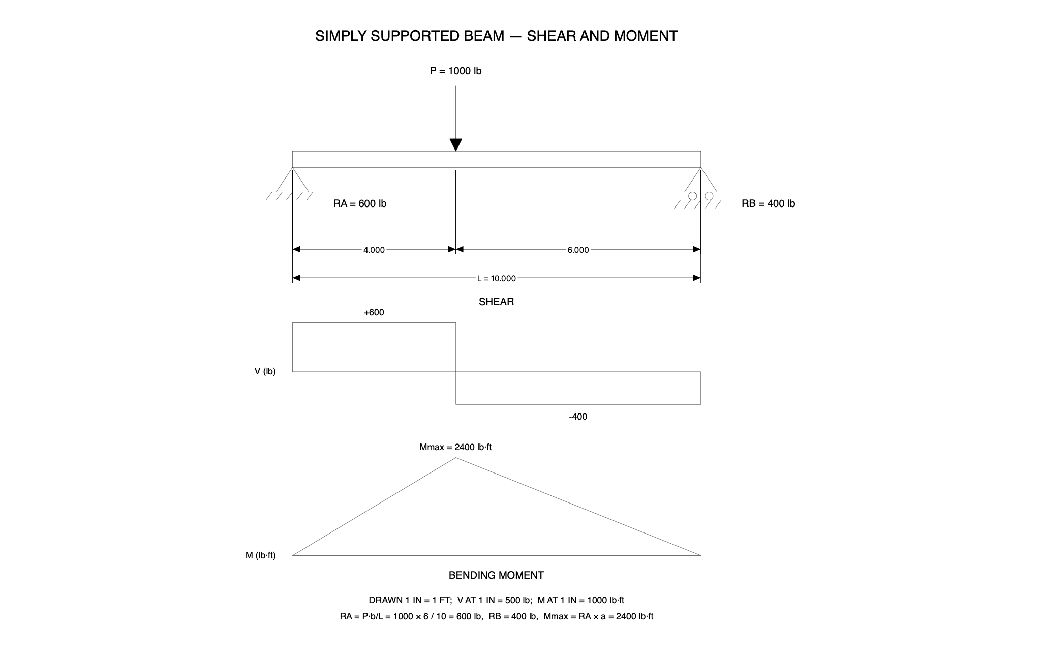
Set the dimension text height to 0.2 first. THE BEAM: a rectangle from 0, 0 with width 10 and height 0.4. A pin support at the left end: an open triangle with apex 0, 0 and base corners -0.4, -0.6 and 0.4, -0.6, a ground line from -0.7, -0.6 to 0.7, -0.6, and five hatch ticks under it, each from a point on the ground line down-left to 0.15 left and 0.2 below, at x = -0.5, -0.25, 0, 0.25 and 0.5. A roller support at the right end: an open triangle with apex 10, 0 and base corners 9.6, -0.6 and 10.4, -0.6, two circles of radius 0.1 at 9.8, -0.7 and 10.2, -0.7, a ground line from 9.3, -0.8 to 10.7, -0.8, and five hatch ticks from that line at x = 9.5, 9.75, 10, 10.25 and 10.5. The load: a vertical line from 4, 2.0 down to 4, 0.7 with a FILLED triangle arrowhead — filled solid black, not an outline — corners 3.85, 0.7 and 4.15, 0.7, tip 4, 0.4 on the top of the beam; label "P = 1000 lb" in 0.25-inch text centered at 4, 2.35. Reaction labels in 0.25-inch text, middle-left anchored: "RA = 600 lb" at 1.0, -0.9 and "RB = 400 lb" at 11.0, -0.9. Dimension the load position with horizontal dimensions from 0, 0 to 4, 0 and from 4, 0 to 10, 0, both offset 2.0 below, and the span from 0, 0 to 10, 0 offset 2.7 below with the prefix "L = ". THE SHEAR DIAGRAM: a baseline from 0, -5.0 to 10, -5.0 and a polyline through 0, -5.0 then 0, -3.8 then 4, -3.8 then 4, -5.8 then 10, -5.8 then 10, -5.0. Label "+600" in 0.22-inch text centered at 2, -3.55 and "-400" centered at 7, -6.1; "V (lb)" middle-right anchored at -0.4, -5.0; title "SHEAR" in 0.25-inch text centered at 5, -3.3. THE MOMENT DIAGRAM: a baseline from 0, -9.5 to 10, -9.5 and a polyline through 0, -9.5 then 4, -7.1 then 10, -9.5. Label "Mmax = 2400 lb·ft" in 0.22-inch text centered at 4, -6.85; "M (lb·ft)" middle-right anchored at -0.4, -9.5; title "BENDING MOMENT" in 0.25-inch text centered at 5, -10.0. Title the whole drawing "SIMPLY SUPPORTED BEAM — SHEAR AND MOMENT" in 0.35-inch text centered at 5, 3.2. Two 0.22-inch notes: "DRAWN 1 IN = 1 FT; V AT 1 IN = 500 lb; M AT 1 IN = 1000 lb·ft" centered at 5, -10.6 and "RA = P·b/L = 1000 × 6 / 10 = 600 lb, RB = 400 lb, Mmax = RA × a = 2400 lb·ft" centered at 5, -11.0. Run check_overlaps when you are done and fix anything it flags.”

What C3 drew

Simply supported beam, shear and moment — a C3 drawing produced by C3 Assistant

Pin and roller supports, a point load, and the shear and bending-moment diagrams stacked under the beam, L = 10.000 dimensioned.

19

Venturi meter

Fluid mechanics

The request, verbatim

“Draw a Venturi meter in section with two piezometer tubes, as in a fluid-mechanics text. Show the whole request (433 words)

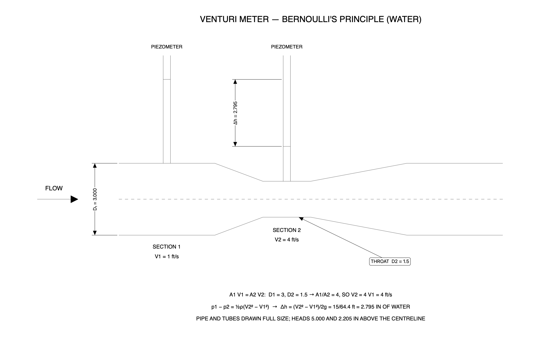
Set the dimension text height to 0.2 first. The pipe centreline is a DASHED line from 0, 0 to 16, 0. The top wall is a polyline through 0, 1.5 then 4, 1.5 then 6, 0.75 then 8, 0.75 then 12, 1.5 then 16, 1.5; the bottom wall is its mirror, a polyline through 0, -1.5 then 4, -1.5 then 6, -0.75 then 8, -0.75 then 12, -1.5 then 16, -1.5. Flow enters from the left: a line from -3.4, 0 to -2.0, 0 with a FILLED triangle arrowhead — filled solid black, not an outline — corners -2.0, -0.15 and -2.0, 0.15, tip -1.7, 0; label "FLOW" in 0.25-inch text centered at -2.7, 0.45. Piezometer tube 1 stands on the inlet: two vertical lines at x = 1.85 and x = 2.15 from y = 1.5 up to y = 6.0, with the water level a short line from 1.85, 5.000 to 2.15, 5.000. Piezometer tube 2 stands on the throat: two vertical lines at x = 6.85 and x = 7.15 from y = 0.75 up to y = 6.0, with the water level a short line from 6.85, 2.205 to 7.15, 2.205. Label both "PIEZOMETER" in 0.2-inch text centered at 2, 6.35 and 7, 6.35. Dimension the inlet diameter with a vertical dimension from 0, -1.5 to 0, 1.5 offset 1.0 to the left, prefix "D1 = ". Dimension the head difference with a vertical dimension from 6.85, 2.205 to 6.85, 5.000 offset 2.0 to the left, prefix "Δh = ". Call out the throat with a leader reading "THROAT D2 = 1.5" with its text at 10.5, -2.6 and its arrow on the throat wall at 7.5, -0.75. Section labels in 0.22-inch text: "SECTION 1" centered at 2, -2.0 and "V1 = 1 ft/s" at 2, -2.4; "SECTION 2" centered at 7, -1.3 and "V2 = 4 ft/s" at 7, -1.7. Title "VENTURI METER — BERNOULLI'S PRINCIPLE (WATER)" in 0.35-inch text centered at 8, 7.5. Three 0.22-inch notes centered at x = 8: "A1 V1 = A2 V2: D1 = 3, D2 = 1.5 → A1/A2 = 4, SO V2 = 4 V1 = 4 ft/s" at y = -4.0; "p1 − p2 = ½ρ(V2² − V1²) → Δh = (V2² − V1²)/2g = 15/64.4 ft = 2.795 IN OF WATER" at y = -4.5; "PIPE AND TUBES DRAWN FULL SIZE; HEADS 5.000 AND 2.205 IN ABOVE THE CENTRELINE" at y = -5.0. Run check_overlaps when you are done and fix anything it flags.”

What C3 drew

Venturi meter — a C3 drawing produced by C3 Assistant

A pipe necking to a throat, two piezometer tubes with the head visibly lower at the throat, Δh dimensioned at 2.795, a leader on the throat.

20

Phasor diagram, series RL circuit

Electrical engineering

The request, verbatim

“Draw a phasor diagram for a series RL circuit, head to tail, the way an AC-circuits text draws it. Show the whole request (323 words)

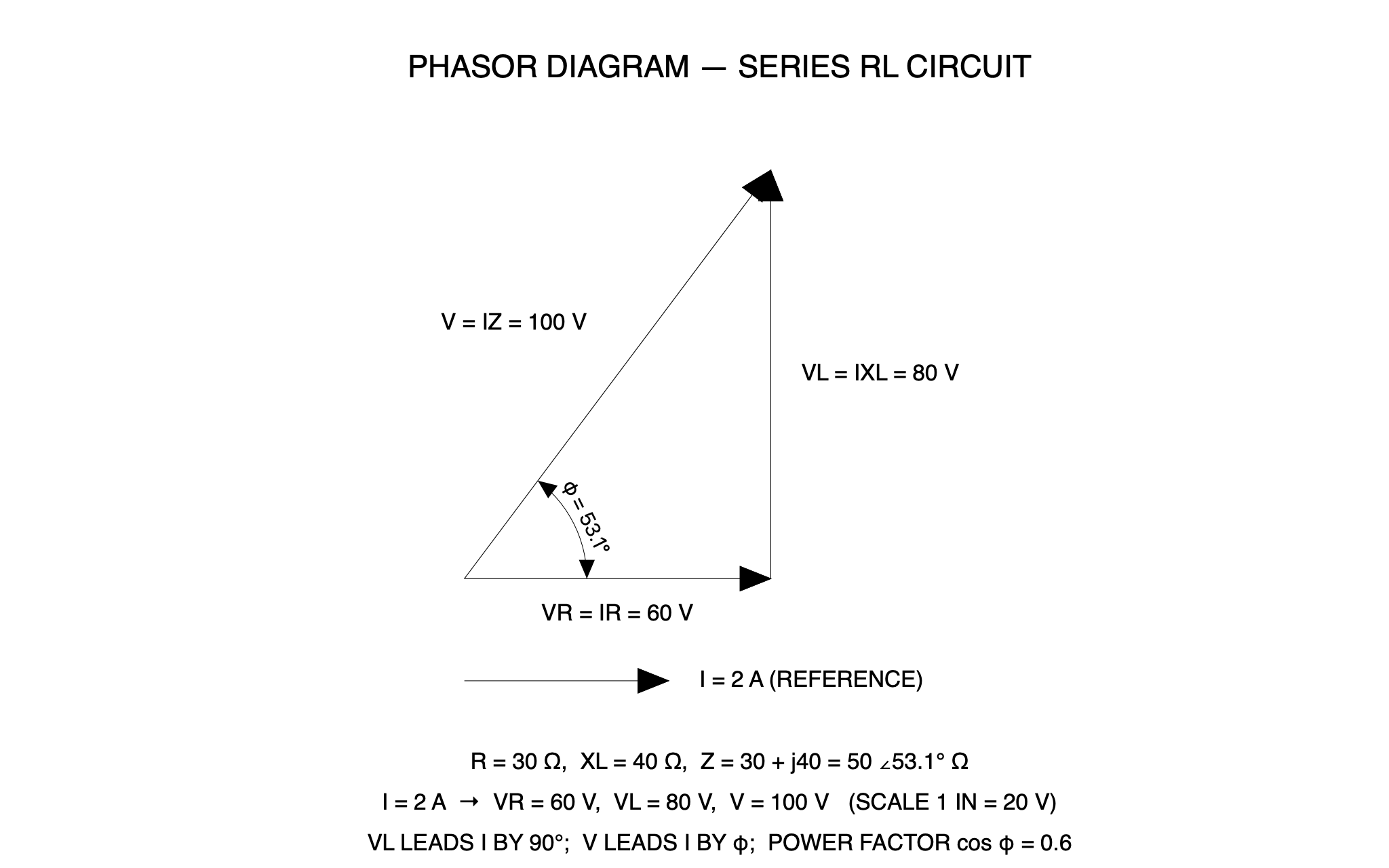
Phasors are a line plus a FILLED triangle arrowhead — filled solid black, not an outline. VR along the reference direction: a line from 0, 0 to 2.7, 0, arrowhead corners 2.7, -0.12 and 2.7, 0.12, tip 3, 0. VL from the tip of VR straight up: a line from 3, 0 to 3, 3.7, arrowhead corners 2.88, 3.7 and 3.12, 3.7, tip 3, 4. The resultant V from the origin to the tip of VL: a line from 0, 0 to 2.82, 3.76, arrowhead corners 2.724, 3.832 and 2.916, 3.688, tip 3, 4. The current phasor below, along the same reference direction: a line from 0, -1.0 to 1.7, -1.0, arrowhead corners 1.7, -1.12 and 1.7, -0.88, tip 2, -1.0. Labels in 0.22-inch text: "VR = IR = 60 V" centered at 1.5, -0.35; "VL = IXL = 80 V" middle-left anchored at 3.3, 2.0; "V = IZ = 100 V" middle-right anchored at 1.2, 2.5; "I = 2 A (REFERENCE)" middle-left anchored at 2.3, -1.0. Dimension the phase angle with an angular dimension between the VR line and the V line at the origin, arc 1.2 inches from the origin, prefix "φ = " — it must read φ = 53.1°. Title "PHASOR DIAGRAM — SERIES RL CIRCUIT" in 0.3-inch text centered at 2.5, 5.0. Three 0.22-inch notes centered at x = 2.5: "R = 30 Ω, XL = 40 Ω, Z = 30 + j40 = 50 ∠53.1° Ω" at y = -1.8; "I = 2 A → VR = 60 V, VL = 80 V, V = 100 V (SCALE 1 IN = 20 V)" at y = -2.2; "VL LEADS I BY 90°; V LEADS I BY φ; POWER FACTOR cos φ = 0.6" at y = -2.6. Run check_overlaps when you are done and fix anything it flags.”

What C3 drew

Phasor diagram, series RL circuit — a C3 drawing produced by C3 Assistant

A 3-4-5 triangle of head-to-tail phasors with the phase angle dimensioned at 53.1° and the current phasor below as the reference.

21

Current vector triangle, set and drift

Marine navigation

The request, verbatim

“Draw a marine navigation vector triangle for set and drift, as on a plotting sheet. Show the whole request (323 words)

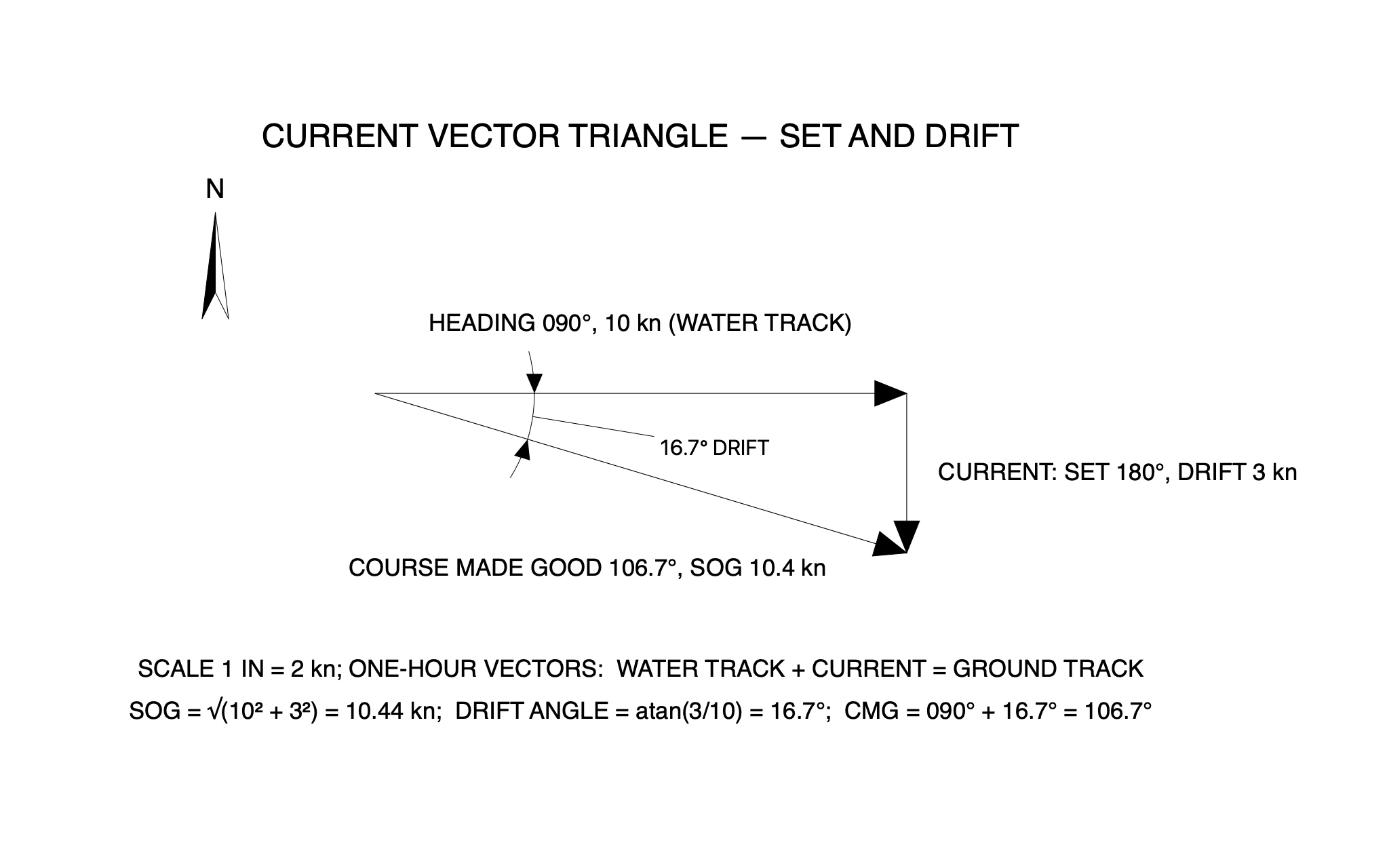
Set the dimension text height to 0.2 first. Three vectors, each a line plus a FILLED triangle arrowhead — filled solid black, not an outline. The heading (water track), 090° at 10 kn: a line from 0, 0 to 4.7, 0, arrowhead corners 4.7, -0.12 and 4.7, 0.12, tip 5, 0. The current, set 180° drift 3 kn, from the end of the heading vector: a line from 5, 0 to 5, -1.2, arrowhead corners 4.88, -1.2 and 5.12, -1.2, tip 5, -1.5. The ground track from the origin to the end of the current vector: a line from 0, 0 to 4.712, -1.414, arrowhead corners 4.746, -1.299 and 4.678, -1.529, tip 5, -1.5. Labels in 0.22-inch text: "HEADING 090°, 10 kn (WATER TRACK)" centered at 2.5, 0.65; "CURRENT: SET 180°, DRIFT 3 kn" middle-left anchored at 5.3, -0.75; "COURSE MADE GOOD 106.7°, SOG 10.4 kn" centered at 2.0, -1.65. Dimension the drift angle with an angular dimension between the heading line and the ground-track line at the origin, arc 1.5 inches from the origin, suffix " DRIFT", with its text centered at 3.2, -0.5 — inside the angle, further out where the corner is wide enough to hold it — reading horizontally; C3 draws a leader from the arc to the text. It must read 16.7° DRIFT. Put a north arrow centered at -1.5, 1.2, 1 inch tall. Title "CURRENT VECTOR TRIANGLE — SET AND DRIFT" in 0.3-inch text centered at 2.5, 2.4. Two 0.22-inch notes centered at x = 2.5: "SCALE 1 IN = 2 kn; ONE-HOUR VECTORS: WATER TRACK + CURRENT = GROUND TRACK" at y = -2.6 and "SOG = √(10² + 3²) = 10.44 kn; DRIFT ANGLE = atan(3/10) = 16.7°; CMG = 090° + 16.7° = 106.7°" at y = -3.0. Run check_overlaps when you are done and fix anything it flags.”

What C3 drew

Current vector triangle, set and drift — a C3 drawing produced by C3 Assistant

Heading, current and ground-track vectors, a north arrow, and an angular dimension whose text was moved clear of the narrow corner with a leader.

22

Finite-state machine, turnstile

Computer science

The request, verbatim

“Draw the state diagram of a turnstile, a finite-state machine, as in a computer-science text. Show the whole request (336 words)

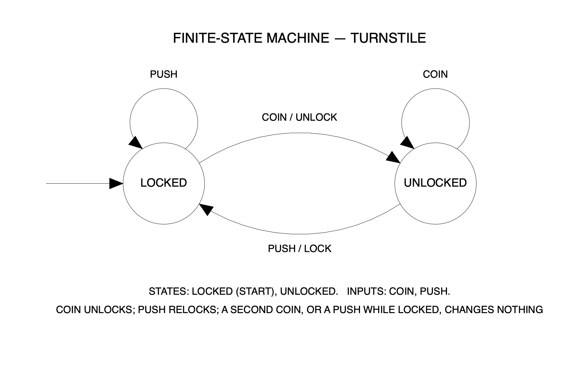
Two states are circles of radius 0.9: LOCKED centered at 0, 0 and UNLOCKED centered at 6, 0, with their names in 0.25-inch text centered on the circle centres. Every arrowhead below is a FILLED triangle polygon — create it filled, solid black, not an outline. The start arrow: a line from -2.6, 0 to -1.2, 0 with an arrowhead of corners -1.2, -0.12 and -1.2, 0.12 and tip -0.9, 0. Transition COIN from LOCKED to UNLOCKED, curving over the top: an arc centered at 3, -2.877 with radius 4 from 56.3 to 123.7 degrees, arrowhead at its right end with tip 5.221, 0.45 and corners 5.038, 0.716 and 4.904, 0.517; label "COIN / UNLOCK" in 0.22-inch text centered at 3, 1.45. Transition PUSH from UNLOCKED back to LOCKED, curving under: an arc centered at 3, 2.877 with radius 4 from 236.3 to 303.7 degrees, arrowhead at its left end with tip 0.779, -0.45 and corners 0.962, -0.716 and 1.096, -0.517; label "PUSH / LOCK" centered at 3, -1.45. The LOCKED self-loop (push while locked) sits on top of the state: an arc centered at 0, 1.35 with radius 0.75 from 308.9 to 231.1 degrees, arrowhead with tip -0.471, 0.767 and corners -0.629, 1.049 and -0.780, 0.862; label "PUSH" centered at 0, 2.4. The UNLOCKED self-loop (a second coin) is the same loop shifted 6 to the right: an arc centered at 6, 1.35 with radius 0.75 from 308.9 to 231.1 degrees, arrowhead with tip 5.529, 0.767 and corners 5.371, 1.049 and 5.220, 0.862; label "COIN" centered at 6, 2.4. Title "FINITE-STATE MACHINE — TURNSTILE" in 0.3-inch text centered at 3, 3.2. Two 0.22-inch notes centered at x = 3: "STATES: LOCKED (START), UNLOCKED. INPUTS: COIN, PUSH." at y = -2.4 and "COIN UNLOCKS; PUSH RELOCKS; A SECOND COIN, OR A PUSH WHILE LOCKED, CHANGES NOTHING" at y = -2.8. Run check_overlaps when you are done and fix anything it flags.”

What C3 drew

Finite-state machine, turnstile — a C3 drawing produced by C3 Assistant

Two states, two transition arcs, a self-loop on each state, a start arrow, every arrowhead filled.

23

Cladogram of six vertebrates

Biology

The request, verbatim

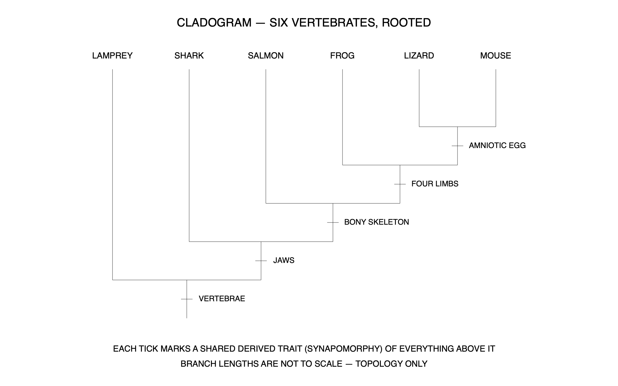
“Draw a cladogram of six vertebrates as an evolutionary biologist draws it, with right-angle branches, tips at the top and the root at the bottom. Show the whole request (361 words)

Tip stems are vertical lines: LAMPREY from 0, 6 down to 0, 0.5; SHARK from 2, 6 down to 2, 1.5; SALMON from 4, 6 down to 4, 2.5; FROG from 6, 6 down to 6, 3.5; LIZARD from 8, 6 down to 8, 4.5; MOUSE from 10, 6 down to 10, 4.5. Node bars are horizontal lines: from 8, 4.5 to 10, 4.5; from 6, 3.5 to 9, 3.5; from 4, 2.5 to 7.5, 2.5; from 2, 1.5 to 5.75, 1.5; from 0, 0.5 to 3.875, 0.5. Node stems are vertical lines dropping from the middle of each bar to the next bar down: from 9, 4.5 to 9, 3.5; from 7.5, 3.5 to 7.5, 2.5; from 5.75, 2.5 to 5.75, 1.5; from 3.875, 1.5 to 3.875, 0.5; and the root from 1.9375, 0.5 down to 1.9375, -0.5. Label the tips in 0.22-inch text centered 0.35 above each tip: "LAMPREY" at 0, 6.35; "SHARK" at 2, 6.35; "SALMON" at 4, 6.35; "FROG" at 6, 6.35; "LIZARD" at 8, 6.35; "MOUSE" at 10, 6.35. Mark the shared derived trait on each stem with a short horizontal tick 0.3 wide crossing the stem at its midpoint, and the trait name in 0.2-inch text middle-left anchored 0.3 to the right of the stem: tick from 8.85, 4.0 to 9.15, 4.0 with "AMNIOTIC EGG" at 9.3, 4.0; tick from 7.35, 3.0 to 7.65, 3.0 with "FOUR LIMBS" at 7.8, 3.0; tick from 5.6, 2.0 to 5.9, 2.0 with "BONY SKELETON" at 6.05, 2.0; tick from 3.725, 1.0 to 4.025, 1.0 with "JAWS" at 4.2, 1.0; tick from 1.7875, 0 to 2.0875, 0 with "VERTEBRAE" at 2.25, 0. Title "CLADOGRAM — SIX VERTEBRATES, ROOTED" in 0.3-inch text centered at 5, 7.2. Two 0.22-inch notes centered at x = 5: "EACH TICK MARKS A SHARED DERIVED TRAIT (SYNAPOMORPHY) OF EVERYTHING ABOVE IT" at y = -1.3 and "BRANCH LENGTHS ARE NOT TO SCALE — TOPOLOGY ONLY" at y = -1.7. Run check_overlaps when you are done and fix anything it flags.”

What C3 drew

Cladogram of six vertebrates — a C3 drawing produced by C3 Assistant

Right-angle branches from the root to six tips, a tick on each stem naming the shared derived trait.

24

Phase diagram of water

Physical chemistry

The request, verbatim

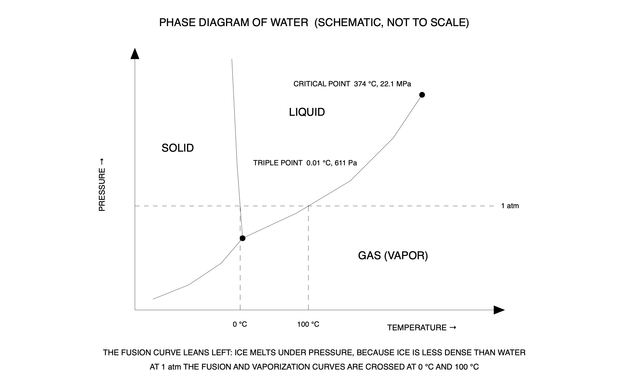
“Draw the phase diagram of water, schematic, as in a physical-chemistry text. Show the whole request (384 words)

Axes: the temperature axis a line from 0, 0 to 10, 0 with a FILLED triangle arrowhead — filled solid black, not an outline — corners 10, -0.12 and 10, 0.12, tip 10.3, 0; the pressure axis a line from 0, 0 to 0, 7 with arrowhead corners -0.12, 7 and 0.12, 7, tip 0, 7.3. Axis titles in 0.22-inch text: "TEMPERATURE →" centered at 8, -0.5 and "PRESSURE →" rotated 90 degrees centered at -0.9, 3.5. The sublimation curve is a polyline through 0.5, 0.3 then 1.5, 0.7 then 2.4, 1.3 then 3, 2. The vaporization curve is a polyline through 3, 2 then 4.5, 2.7 then 6, 3.6 then 7.2, 4.8 then 8, 6. The fusion curve leans to the left as it rises: a polyline through 3, 2 then 2.85, 4 then 2.7, 7. Mark the triple point with a filled circle of radius 0.08 at 3, 2 and the critical point with a filled circle of radius 0.08 at 8, 6. Region labels in 0.3-inch text: "SOLID" centered at 1.2, 4.5; "LIQUID" centered at 4.8, 5.5; "GAS (VAPOR)" centered at 7.2, 1.5. Point labels in 0.2-inch text: "TRIPLE POINT 0.01 °C, 611 Pa" middle-left anchored at 3.3, 1.6; "CRITICAL POINT 374 °C, 22.1 MPa" middle-right anchored at 7.7, 6.3. The 1 atm line: a DASHED horizontal line from 0, 2.9 to 10, 2.9 labelled "1 atm" in 0.2-inch text middle-left anchored at 10.2, 2.9. Where it crosses the fusion curve, at 2.933, 2.9, and the vaporization curve, at 4.833, 2.9, drop DASHED vertical lines to the temperature axis — from 2.933, 2.9 to 2.933, 0 and from 4.833, 2.9 to 4.833, 0 — and label them "0 °C" centered at 2.93, -0.4 and "100 °C" centered at 4.83, -0.4 in 0.2-inch text. Title "PHASE DIAGRAM OF WATER (SCHEMATIC, NOT TO SCALE)" in 0.3-inch text centered at 5, 8.0. Two 0.22-inch notes centered at x = 5: "THE FUSION CURVE LEANS LEFT: ICE MELTS UNDER PRESSURE, BECAUSE ICE IS LESS DENSE THAN WATER" at y = -1.2 and "AT 1 atm THE FUSION AND VAPORIZATION CURVES ARE CROSSED AT 0 °C AND 100 °C" at y = -1.6. Run check_overlaps when you are done and fix anything it flags.”

What C3 drew

Phase diagram of water — a C3 drawing produced by C3 Assistant

Sublimation, vaporization and fusion curves meeting at the triple point, the fusion curve leaning left, the 1 atm line dropped to 0 °C and 100 °C.

25

Uranium-238 decay series

Nuclear physics

The request, verbatim

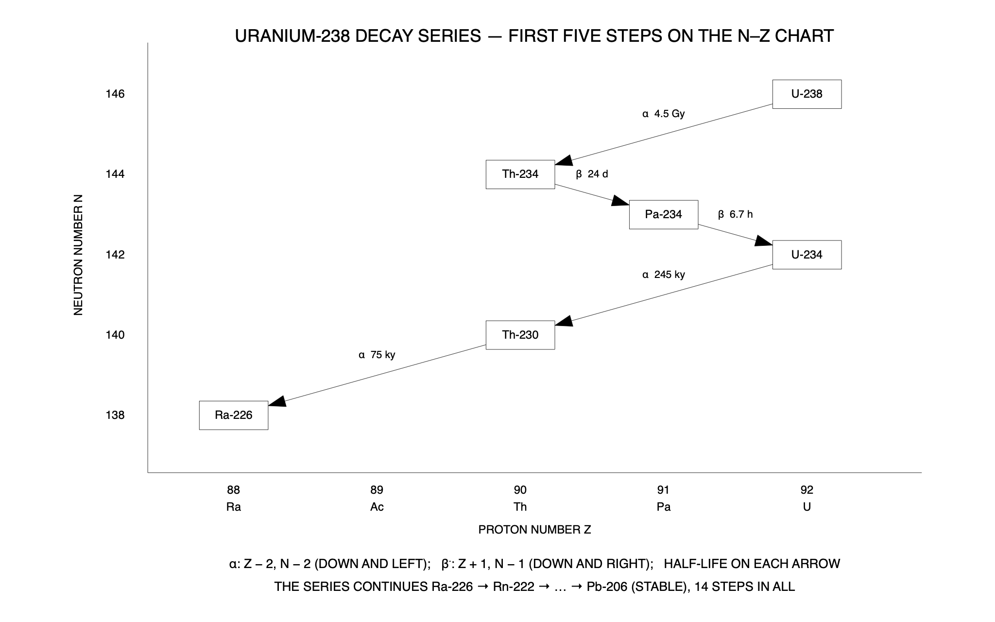
“Draw the first five steps of the uranium-238 decay series on a chart of neutron number against proton number, as in a nuclear-physics text. Show the whole request (431 words)

Each nuclide is a rectangle 1.2 wide and 0.5 tall with its name in 0.2-inch text centered inside: U-238 with lower-left corner 9.4, 5.35; Th-234 at 4.4, 3.95; Pa-234 at 6.9, 3.25; U-234 at 9.4, 2.55; Th-230 at 4.4, 1.15; Ra-226 at -0.6, -0.25. Decay arrows run from the edge of one box to the edge of the next, each a line plus a FILLED triangle arrowhead — filled solid black, not an outline: U-238 to Th-234, line from 9.4, 5.432 to 5.889, 4.449, arrowhead corners 5.916, 4.353 and 5.862, 4.545, tip 5.6, 4.368; Th-234 to Pa-234, line from 5.6, 4.032 to 6.611, 3.749, corners 6.638, 3.845 and 6.584, 3.653, tip 6.9, 3.668; Pa-234 to U-234, line from 8.1, 3.332 to 9.111, 3.049, corners 9.138, 3.145 and 9.084, 2.953, tip 9.4, 2.968; U-234 to Th-230, line from 9.4, 2.632 to 5.889, 1.649, corners 5.916, 1.553 and 5.862, 1.745, tip 5.6, 1.568; Th-230 to Ra-226, line from 4.4, 1.232 to 0.889, 0.249, corners 0.916, 0.153 and 0.862, 0.345, tip 0.6, 0.168. Label each arrow in 0.18-inch text centered just above its middle: "α 4.5 Gy" at 7.5, 5.25; "β 24 d" at 6.25, 4.2; "β 6.7 h" at 8.75, 3.5; "α 245 ky" at 7.5, 2.45; "α 75 ky" at 2.5, 1.05. Axes: a line from -1.5, -1.0 to 12, -1.0 and a line from -1.5, -1.0 to -1.5, 6.5. Along the bottom, in 0.2-inch text, the proton numbers "88", "89", "90", "91", "92" centered at x = 0, 2.5, 5, 7.5, 10 on y = -1.3, and the element symbols "Ra", "Ac", "Th", "Pa", "U" at the same x on y = -1.6; the axis title "PROTON NUMBER Z" centered at 5.25, -2.0. Up the left, the neutron numbers "138", "140", "142", "144", "146" middle-right anchored at x = -1.9 on y = 0, 1.4, 2.8, 4.2, 5.6; the axis title "NEUTRON NUMBER N" rotated 90 degrees centered at -2.7, 2.8. Title "URANIUM-238 DECAY SERIES — FIRST FIVE STEPS ON THE N–Z CHART" in 0.3-inch text centered at 5.25, 6.6. Two 0.22-inch notes centered at x = 5.25: "α: Z − 2, N − 2 (DOWN AND LEFT); β⁻: Z + 1, N − 1 (DOWN AND RIGHT); HALF-LIFE ON EACH ARROW" at y = -2.6 and "THE SERIES CONTINUES Ra-226 → Rn-222 → … → Pb-206 (STABLE), 14 STEPS IN ALL" at y = -3.0. Run check_overlaps when you are done and fix anything it flags.”

What C3 drew

Uranium-238 decay series — a C3 drawing produced by C3 Assistant

Six nuclides boxed on an N–Z chart, alpha and beta arrows running box edge to box edge, a half-life on every arrow.

26

Head proportions, front view

Art instruction

The request, verbatim

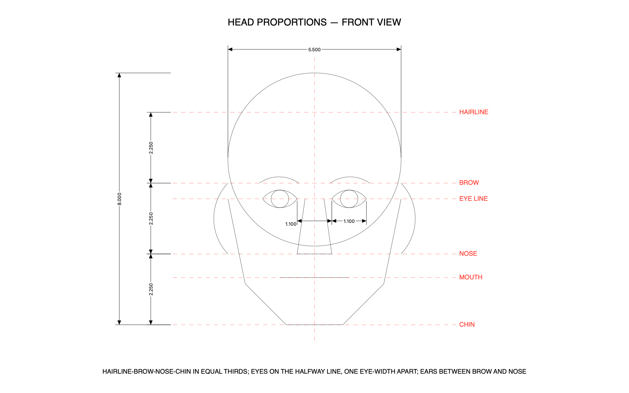
“Draw a front-view head proportion diagram, the kind an art teacher sketches: an 8-inch head with the chin on the origin, and the guide lines that place the features. Show the whole request (471 words)

Everything below is in inches, X across and Y up. Head: a circle for the cranium, center (0, 5.25) radius 2.75, so the top of the skull is at y = 8 and the sides at x = ±2.75. The jaw is one polyline from (-2.75, 4.0) down through (-2.2, 1.3) to the chin at (-0.9, 0), across to (0.9, 0), up through (2.2, 1.3) to (2.75, 4.0). Guide lines, dashed, red, each from x = -4.5 to x = 4.5, with its name in 0.2-inch red text just past the right end: HAIRLINE at y = 6.75, BROW at y = 4.5, EYE LINE at y = 4.0, NOSE at y = 2.25, MOUTH at y = 1.5, CHIN at y = 0. A dashed red vertical centerline from (0, -0.5) to (0, 8.5). Features, black: irises as circles radius 0.28 centered at (-1.1, 4.0) and (1.1, 4.0); each eye outline an upper arc and a lower arc between the eye's inner corner and outer corner, corners at x = ±0.55 and x = ±1.65 on the eye line, each arc bulging 0.28 away from the line. Brows as arcs from (±0.5, 4.5) to (±1.75, 4.5) bulging 0.2 upward. Nose: a line from (-0.3, 4.0) to (-0.55, 2.25), a line from (0.3, 4.0) to (0.55, 2.25), and the base from (-0.55, 2.25) to (0.55, 2.25). Mouth: a line from (-1.1, 1.5) to (1.1, 1.5). Ears: an arc on each side from (±2.75, 4.5) to (±2.75, 2.25) bulging 0.45 outward. Dimensions. The stacked thirds go on the LEFT, anchored at the left ends of the guide lines (x = -4.5) so the extension lines stay short: CHIN to NOSE, NOSE to BROW, BROW to HAIRLINE, dimension line at x = -5.2, each reading 2.25. The overall CHIN to top of skull, anchored at (-4.5, 0) and (-4.5, 8), dimension line at x = -6.2, reading 8.00. The width across the cranium, anchored at (-2.75, 5.25) and (2.75, 5.25), dimension line just above the skull at y = 8.6, reading 5.50. Under the eyes, on one dimension line at y = 3.3 with the text above the line: one eye's width from (0.55, 4.0) to (1.65, 4.0) reading 1.10, and the gap between the eyes from (-0.55, 4.0) to (0.55, 4.0) reading 1.10. Do not move any dimension text off its line. Title "HEAD PROPORTIONS — FRONT VIEW" in 0.3-inch text centered at (0, 9.6), and a note "HAIRLINE-BROW-NOSE-CHIN IN EQUAL THIRDS; EYES ON THE HALFWAY LINE, ONE EYE-WIDTH APART; EARS BETWEEN BROW AND NOSE" in 0.2-inch text centered at (0, -1.5). Run check_overlaps when you are done and fix anything it flags.”

What C3 drew

Head proportions, front view — a C3 drawing produced by C3 Assistant

An 8-inch head with six red dashed guide lines, the hairline-brow-nose-chin thirds dimensioned at 2.250 each, the eyes one eye-width apart with both 1.100s on one line, and the features on the lines they belong to.

The Assistant works inside C3. Nothing else changes.

It operates C3’s own tools

The Assistant has no drawing engine of its own. It calls the same drafting operations the menus do, so whatever it creates is C3 geometry on C3 layers, saved in your .cadd file like everything else.

Off by default. Your key, your choice.

The Assistant is switched off until you turn it on. It runs on your own Anthropic or OpenAI API key, or on a customer-controlled endpoint on your own network with external providers disabled. C3 tells you what leaves the machine before you enable it.

Two operators, one drawing

While the Assistant is working, C3 stays yours. Pan, zoom, inspect. When it finishes, C3 brings the new work into view. If you want it gone, one Cmd+Z removes the whole request.

A palette, not a takeover

The Assistant lives in a small movable panel that remembers where you put it. Its border is red while you type and blue while it works. Close it and it keeps working; bring it back from the Files menu or Cmd+;.

Dimensions that stay honest

Dimensions the Assistant places are associative: edit the part and they re-measure. It cannot override a measured value, and neither can anyone else.

Your drawings. Your network. Your AI.

C3 Secure Enterprise points the Assistant at your organization’s own model through a supported API-compatible interface, with external providers disabled. Demonstrated with Wi-Fi off and a locally hosted model on the same Mac. How it works →

Everything else is still C3

Full 2D drafting, layers, layouts, symbols, dynamic blocks, tables, hatching, architectural, surveying and civil tools, GD&T, PCB and Gerber output, DXF/DWG, SVG, PDF. The Assistant is a new way in, not a new program.