Forty Years in the Making

In 1971, John M. Christy moved to Carbondale, Illinois. While in and around the area he started noticing geodesic domes — structures unlike anything he had ever seen. Curious about the form, he looked into the man behind them: R. Buckminster Fuller.

Through a friend, Michael S. Mitchell — who had spent years studying Fuller's work and was close to him personally — Christy was introduced to Bucky in person. Over the following years he attended Fuller's lectures with Mitchell in Carbondale and in other cities around the country, read Fuller's writings on his own, and built models to test what he was learning. One was a four-frequency geodesic dome — roughly two feet across — constructed from Fuller's published chord factors. When Christy brought it to him, Fuller recognized the chord factors immediately. Another was a small cardboard tetrahedron that Fuller personally signed "To John Christy" with a date. Christy still has it.

One line of Fuller's came back enough times in those lectures to burn itself into how Christy thought about his own work: "You can do anything you want to do. All you have to do is learn how to learn." That became the working principle behind everything that followed. By the early 1970s — well before personal computers were affordable — Christy had already begun trying to write CAD software.

In 1975, CAD systems cost $500,000 and filled entire rooms. Christy was a musician and electronics hobbyist who could barely afford the HP equipment he wanted to use. So he taught himself HP BASIC, then Pascal. By 1982 he had built a CAD system on a $3,000 HP desktop that rivaled systems developed by teams of PhDs. Four years later, Hughes Aircraft was using it to design microwave components for satellites. The result was CADD/200-300, published by Tensegrity, Inc. in Chicago. The company name was used with Bucky Fuller's personal permission, on the one condition that Christy include the phrase "The word tensegrity is an invention of R. Buckminster Fuller" whenever the term appears. Christy has honored that wording for the four decades since, and continues to honor it here.

The same approach drove the 2025 rebuild: pick up the new tools (AI-assisted development), apply four decades of domain knowledge, ship in four months.

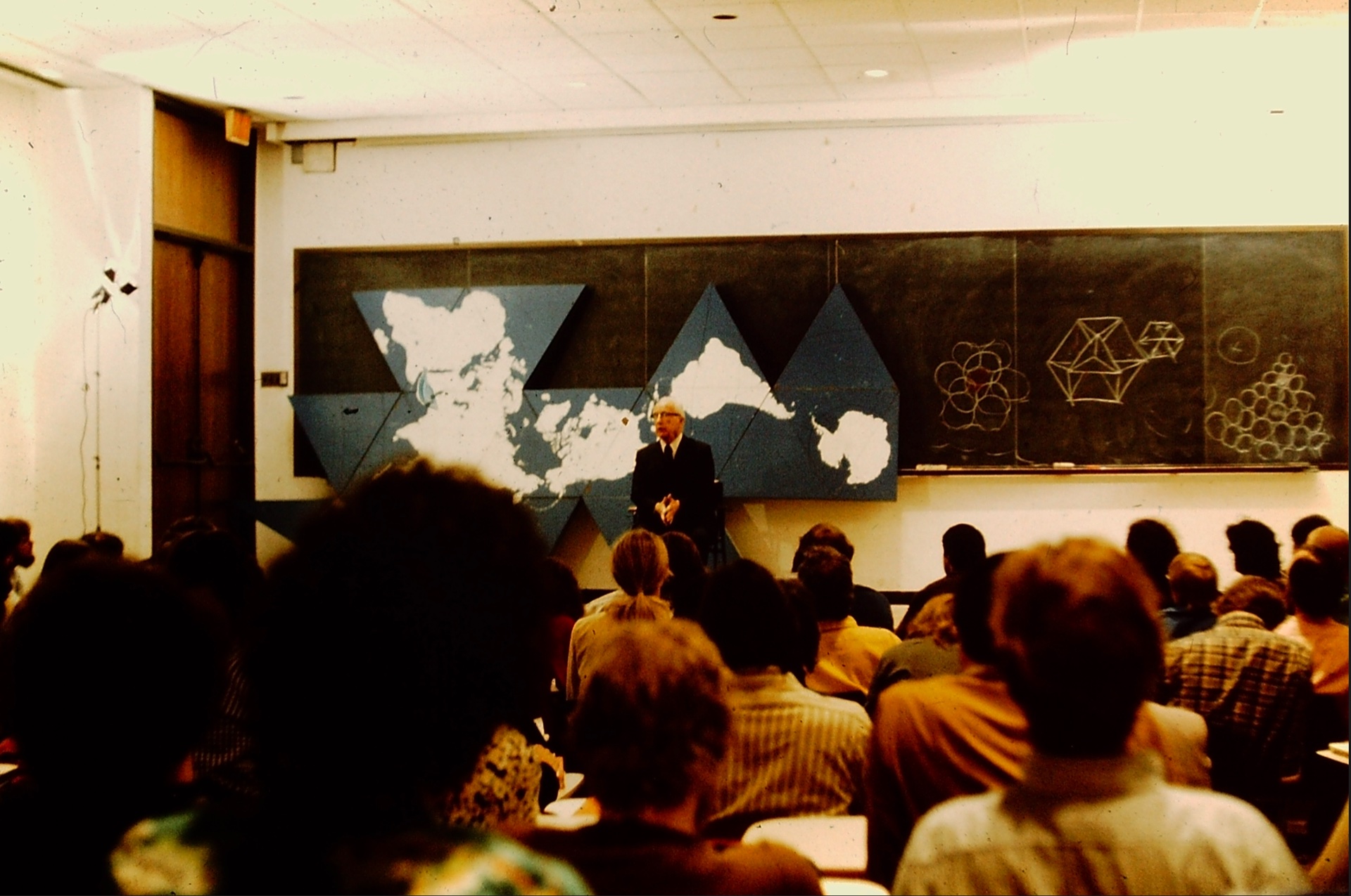
R. Buckminster Fuller at the World Game seminar, University of Pennsylvania. Photo by John M. Christy.

Bucky Fuller at the World Game seminar, University of Pennsylvania, mid-1970s. Photo by John M. Christy.
1971–1980 Christy moves to Carbondale, IL. Studies Fuller's work independently, attends Fuller's lectures, meets him in person several times, builds geodesic and polyhedral models.
1982 First CADD software written for Hewlett-Packard workstations. Published by Tensegrity, Inc., Chicago.
1983 John Hardy adopts CADD for audio engineering at The John Hardy Company, Evanston, IL. Hardy runs it continuously for the next three decades.
1986 Hughes Aircraft validates CADD for satellite microwave design at their Space & Communications Group.
Oct 2025 C3 development begins: native macOS rebuild using SwiftUI, CoreGraphics, and AI-assisted engineering with Claude.
Feb 2026 Feature-complete with DXF interop, Gerber export, Eagle import, SVG export, multi-window, 3D wireframe, and multi-level undo.
Jun–Jul 2026 The AutoCAD-parity wave: running object snaps, window/crossing multi-select, named dimension styles, PDF underlay tracing with scale calibration, area/perimeter inquiry, 100-level undo.

Trusted by Engineers Who Build Satellites

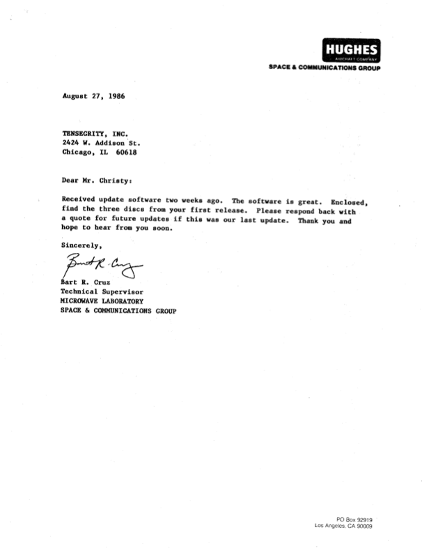
"Thank you for the update software. The software is great."
Bart R. Cruz Technical Supervisor, Microwave Laboratory
Hughes Aircraft Company — Space & Communications Group
August 27, 1986
Original 1986 letter from Hughes Aircraft Space & Communications Group endorsing CADD software
43
Years of continuous development
1
User who never stopped (John Hardy, since 1983)
4
Months to rebuild with AI (Oct 2025 – Feb 2026)

Here’s What CADD/200-300 Users Had to Say

Customer survey responses collected by Tensegrity, Inc., Chicago, IL.

Company Application User Comment
Arizona Public Ser Mechanical & Electrical “Very user friendly; Good package & value; Better than others.”
Bell Comm Research Mechanical & Electrical “Easy to learn; Fast; Easy to go to files and make changes.”
Design Sys/Service Boat & Yacht Designer “Impressed by splines & other useful features; Easy to use.”
Ft Collins Water Plant Blueprints, Electrical “Great support; Faster than PC systems; Great improvements last year.”
Hughes Aircraft Mechanical & Electrical “Very fast; Likes a lot; Bargain; Support excellent; Has 4 copies.”
Ill Switchboard Switching Schematics “Greatest thing since canned beer; Blew other systems tested away.”
Ly-Line Products Lab Furniture/Cabinets “Great! Continually adding upgrades; Liked better than other systems.”
The John Hardy Co PC Board Layout & Mech “Like very much; Very fast; User friendly; Always new features.”
ZYW Corporation Mechanical “Very happy with it; Very fast; Best one tried thus far.”

The Original CADD/200-300 Data Pack (1986)

The original software ran on Hewlett-Packard workstations (HP 216, 217, 310, 320) and cost $4,000 for the first workstation license. It supported HP plotters up to E-size (34"×44"), digitizing tablets for input, and featured the same grid zero + snap increment precision system that C3 uses today.

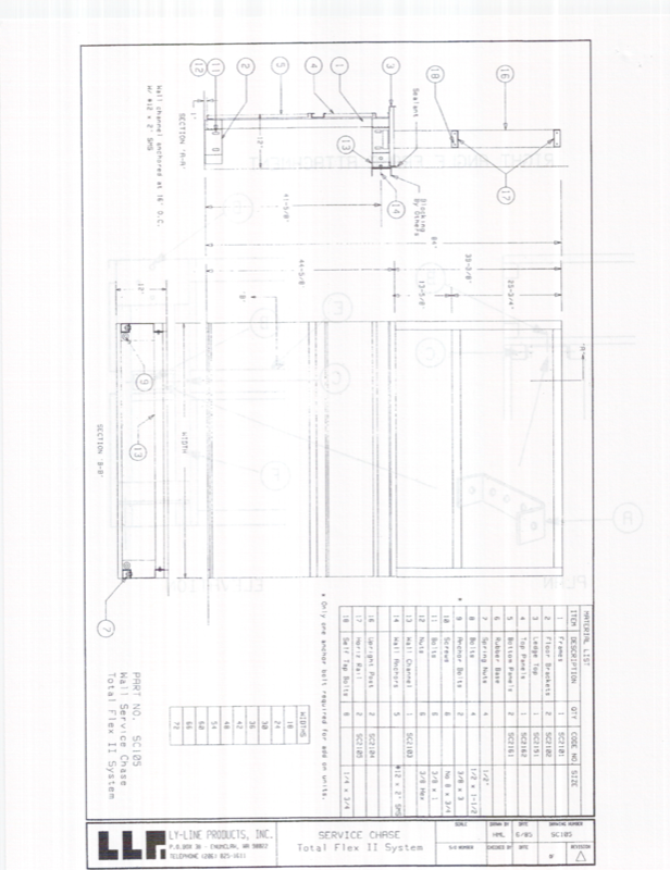
The 1986 data pack includes sample drawings from Hughes Aircraft (satellite microwave assemblies), The John Hardy Company (audio electronics), Ly-Line Products (furniture specifications), and Pfauter (industrial machinery) — showing the range of industries that trusted this software from the beginning.

Published by Tensegrity, Inc. at 2424 Addison Street, Chicago, IL 60618.

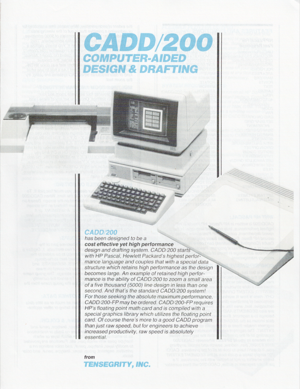
CADD/200 Computer-Aided Design & Drafting brochure — HP workstation with plotter and digitizing tablet, Tensegrity Inc.

Sample Pages from the 24-Page Data Pack

Scroll to browse →

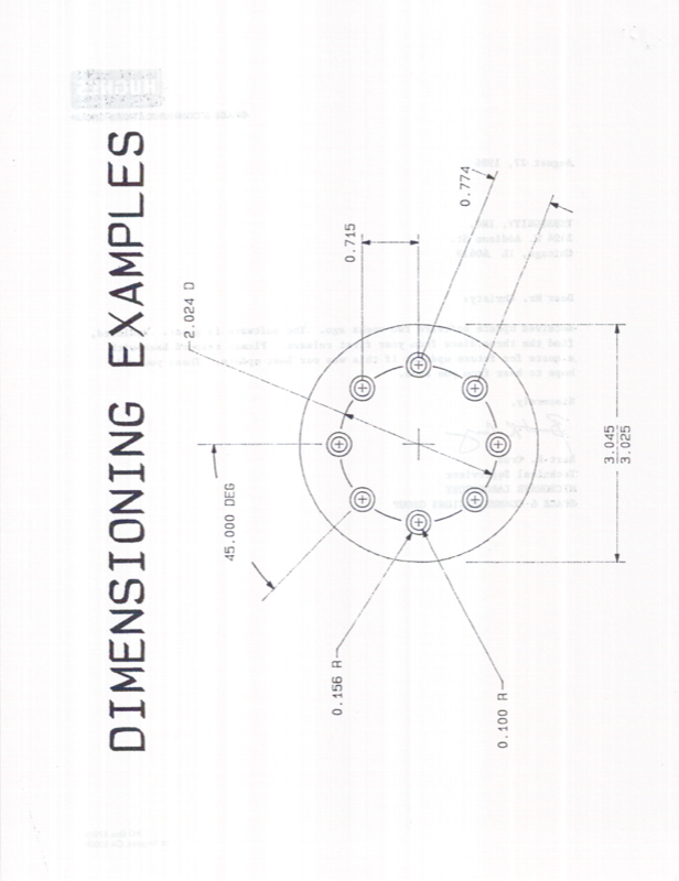
Dimensioning examples — bolt circle with radius, diameter, and angular dimensions

Dimensioning Examples

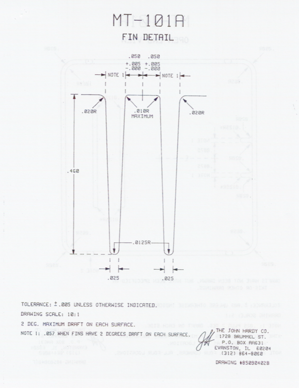
MT-101A Fin Detail — John Hardy Co injection mold part, drawing scale 10:1

Hardy Co — Mold Detail

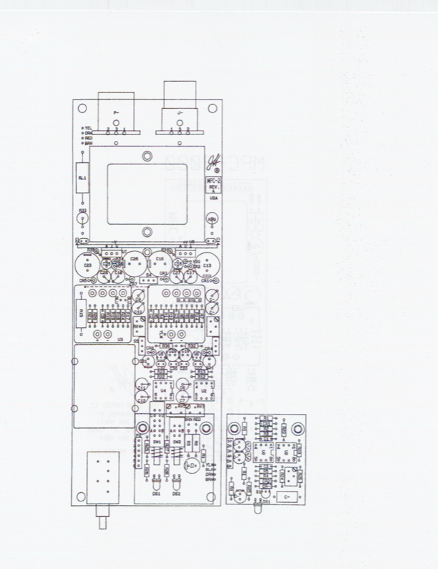
PCB component layout — dense board with ICs, capacitors, resistors, connectors

PCB Component Layout

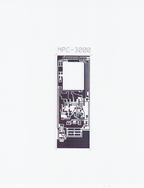
MPC-3000 PCB artwork — copper trace routing for John Hardy preamp board

MPC-3000 PCB Traces

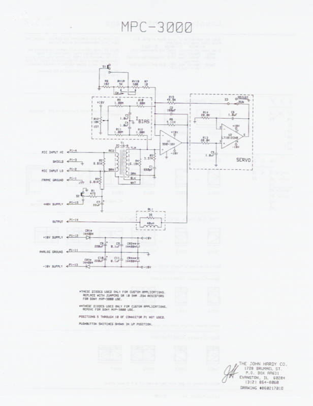
MPC-3000 schematic — BIAS and SERVO circuit sections, John Hardy Co

MPC-3000 Schematic

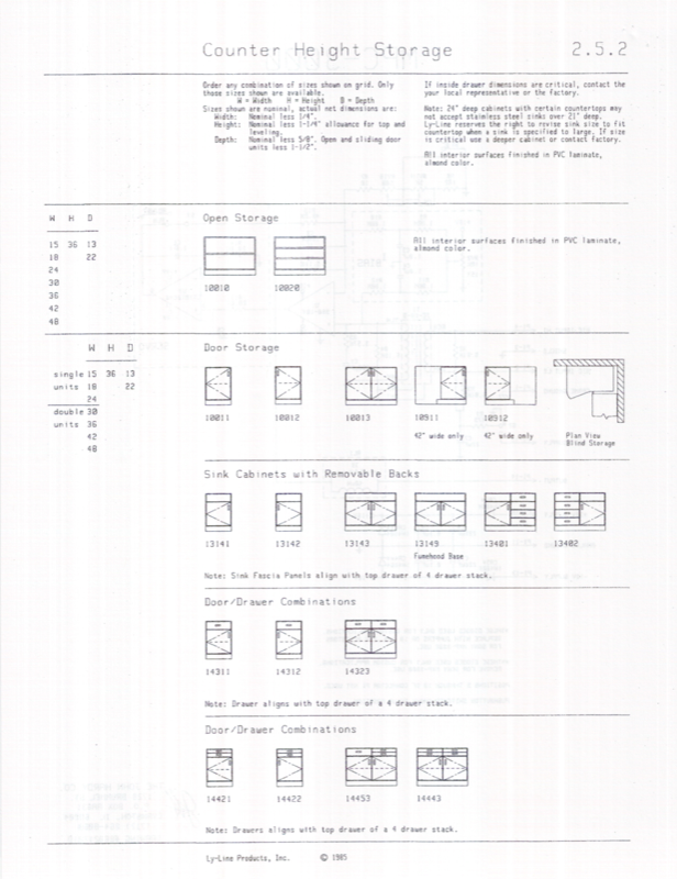
Ly-Line Products counter height storage catalog page, 1985

Ly-Line — Catalog Page

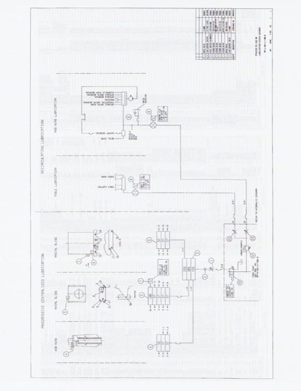
Pfauter lubrication schematic — recirculating and progressive centralized systems

Pfauter — Lubrication

Ly-Line Flex II System full assembly drawing with bill of materials and title block

Ly-Line — Assembly Drawing

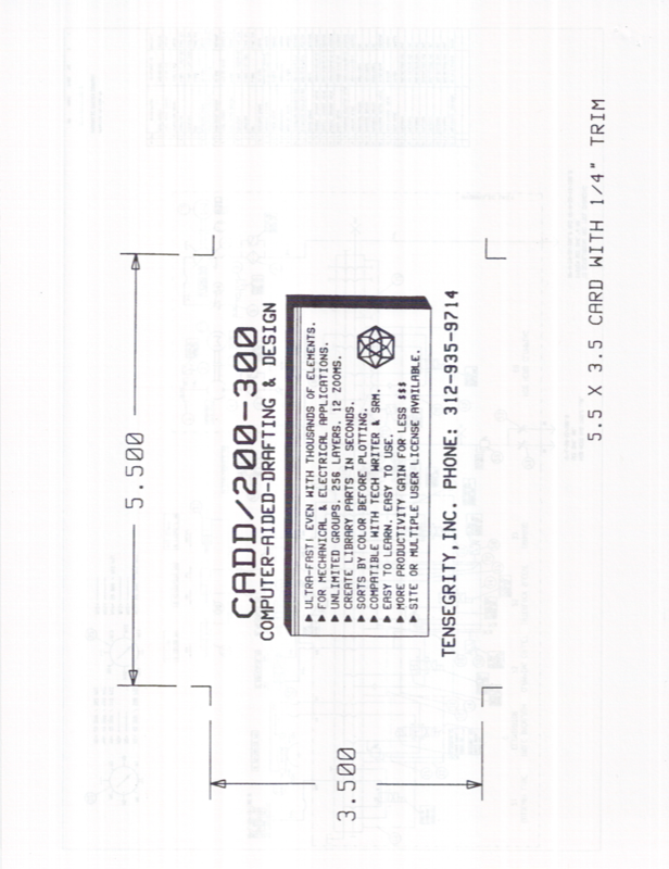
CADD/200-300 business card design — the software drew its own marketing material

Magazine Ad Insert

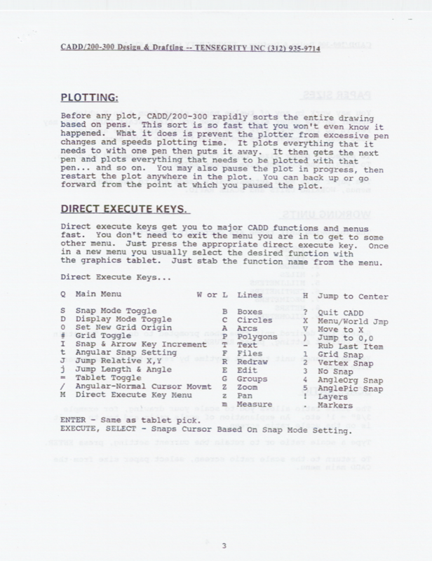
CADD/200-300 Direct Execute Keys reference — same keyboard-driven workflow used in C3 today

Direct Execute Keys (1986)

43 Years of Successive Approximation

Successive approximation is the process by which nature — and engineering — arrives at optimal solutions. You don't leap to perfection. You iterate toward it. Each cycle of design, testing, and refinement eliminates error and reveals a closer approximation of the ideal.

That principle has been the guiding logic behind every revision since CADD/85, and is the discipline at the core of what is now C3.

Early 1980s
CADD/85
First approximation. Established the core problem space and intellectual foundation on HP workstations.
1986–87
CADD/86–87
Refined the model. Tightened methodology, expanded capability. The errors of the first pass became the lessons of the second.
1983–1995
CADD/200–300
Generational leap. Proven at Hughes Aircraft, adopted by Hardy. A mature system that understood its own history well enough to transcend it.
2025–Present
C3
The current approximation. Four decades of wisdom, rebuilt with AI at the speed the methodology always deserved.

The approximation continues.